
Liquid crystal display

a liquid crystal display and display technology, applied in the direction of instruments, lighting support devices, coupling device connections, etc., can solve the problem of increasing the amount of leakage current, and achieve the effect of preventing brightness deterioration and minimizing leakage curren

Inactive Publication Date: 2010-06-15
LG DISPLAY CO LTD
View PDF2 Cites 2 Cited by
  • Summary
  • Abstract
  • Description
  • Claims
  • Application Information

AI Technical Summary

Benefits of technology

[0015]An advantage of the present invention is to provide a liquid crystal display that is adaptive for minimizing a leakage current to prevent brightness deterioration.

Problems solved by technology

As a result, an amount of the leakage current is increased.

Method used


Image

  • Liquid crystal display
  • Liquid crystal display
  • Liquid crystal display

Examples


first embodiment

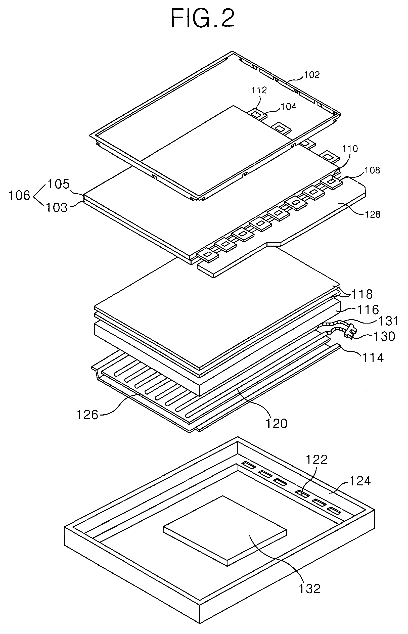
[0028]FIG. 2 is a perspective view showing a liquid crystal display according to the present invention, FIG. 3A is a perspective view showing a rear surface of the liquid crystal display in FIG. 2, and FIG. 3B is a schematic diagram showing a state that a plug connected to the socket in FIG. 3A is connected, via lamp wires, to a lamp.

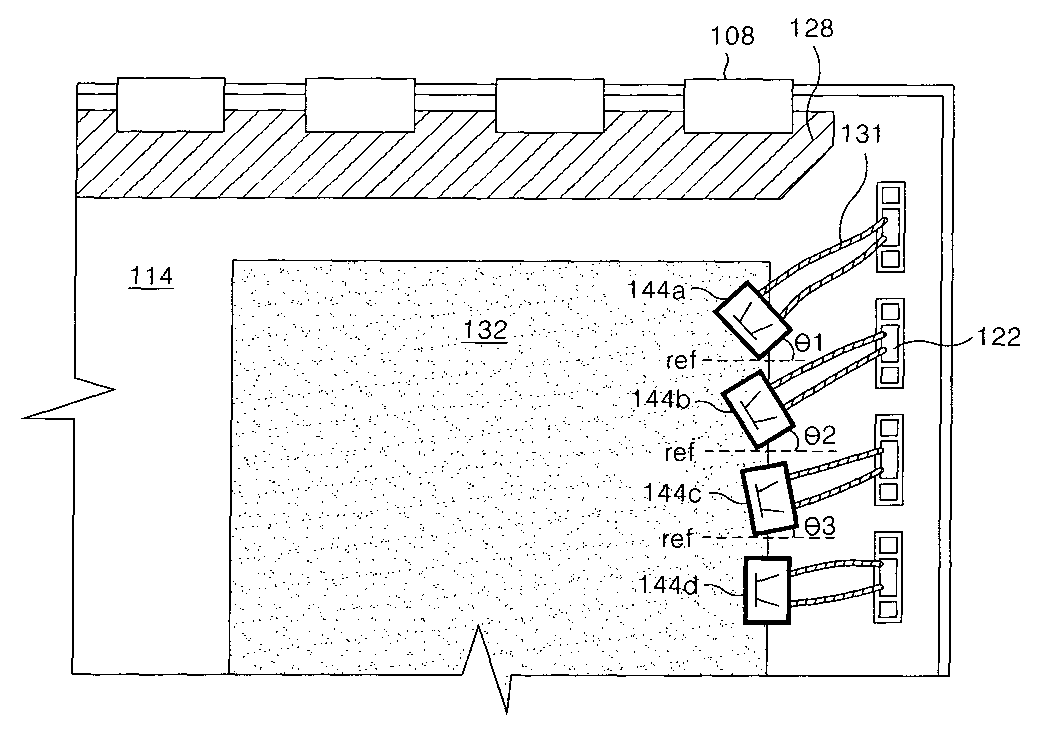
[0029]Referring to FIG. 2, FIG. 3A, and FIG. 3B, the liquid crystal display according to the first embodiment of the present invention includes an uppermost first socket 134a to be inclined at a first angle θ1 to a horizontal reference line ref which is indicated by a dotted line. According to the construction, lengths of the two lamp wires 131 connected to the first socket 134a is substantially the same. The horizontal reference line ref is an imaginary reference line which is perpendicular to a vertical side surface where the output terminals are formed in the inverter circuit board 132.

[0030]The liquid crystal display of the present invention include...

second embodiment

[0046]FIG. 4 is a perspective view showing a rear surface of a liquid crystal display according to the present invention.

[0047]Referring to FIG. 2 and FIG. 4, a liquid crystal display according to the second embodiment of the present invention includes lamp wires 131 drawn out from lamps 120, a inverter circuit board 132 closely arranged at the rear surface of a bottom cover 114 to drive the lamps 120, and sockets 144a, 144b, and 144c connecting the lamp wires 131 drawn out from the lamps 120 to the inverter circuit board 132 and inclined at predetermined angles to a horizontal reference line ref.

[0048]As shown in FIG. 4, the first socket 144a is connected in a posture that a side surface thereof is inclined to have the first angle θ1 to the horizontal reference line ref, to the inverter circuit board 132. The second socket 144b is located under the first socket 144a and is connected to the inverter circuit board 132 in a posture that a side surface thereof is inclined to have a sec...


PUM


Abstract

A liquid crystal display for minimizing a leakage current to prevent brightness deterioration is disclosed. The liquid crystal display includes a backlight unit including a plurality of lamps, a plurality of lamp wires connected to the plurality lamps, and a bottom cover in which the lamps are received, the bottom cover having a plurality of holes through which the lamp wires are passed, an inverter circuit board generating a power to drive the lamps and a plurality of sockets connected to output terminals of the inverter circuit board and connecting to the lamp wires, wherein at least one socket among the sockets is inclined at a side of the inverter circuit board.

Description

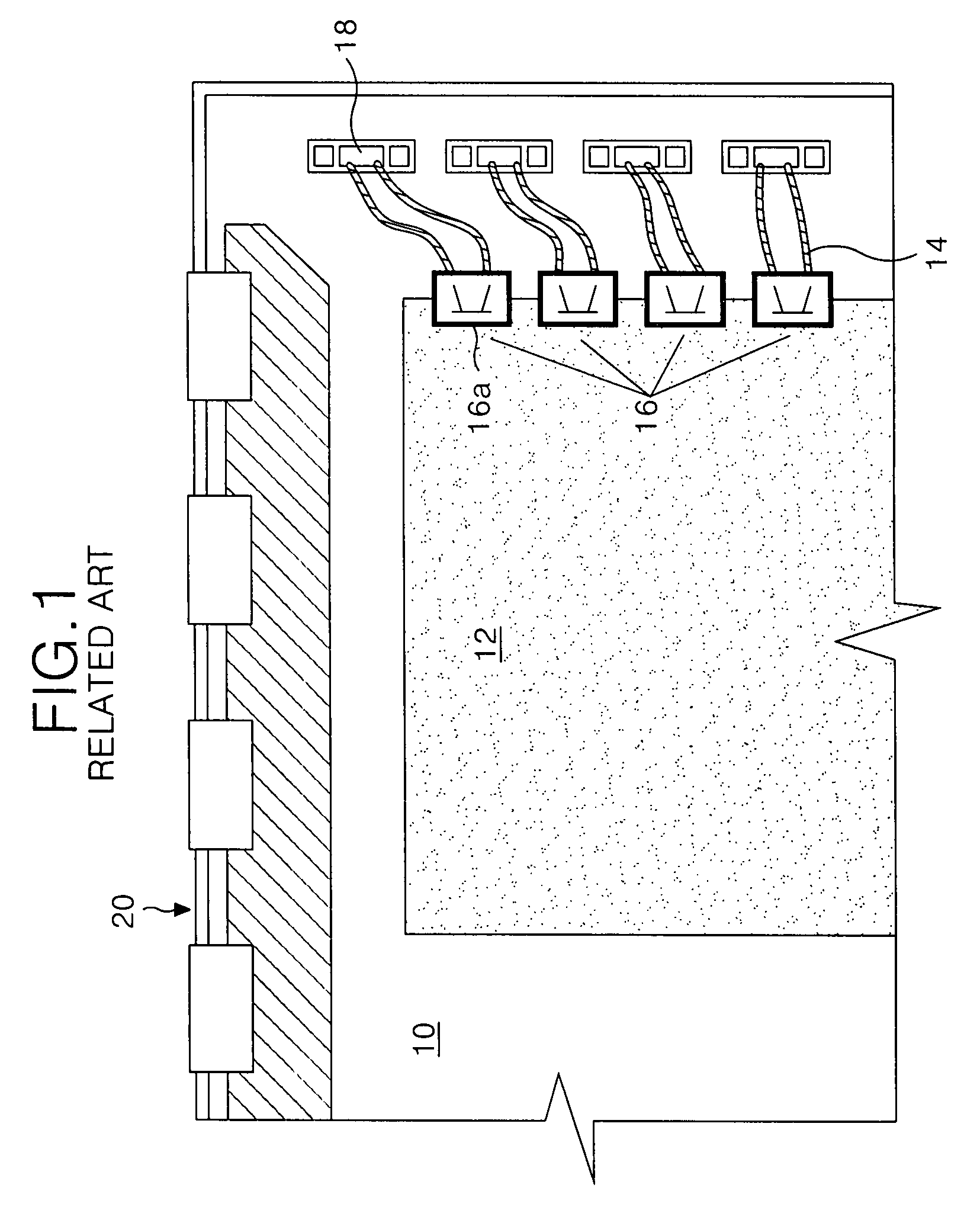
[0001]This application claims the benefit of Korean Patent Application No. P2006-114581 filed in Korea on Nov. 20, 2006, which is hereby incorporated by reference for all purposes as if fully set forth herein.BACKGROUND OF THE INVENTION[0002]1. Field of the Invention[0003]The present invention relates to a liquid crystal display, and more particularly to a liquid crystal display that is adaptive for minimizing a leakage current to prevent brightness deterioration.[0004]2. Description of the Related Art[0005]Generally, a liquid crystal display device is widely used due to its characteristics of light weight, thin profile, low power consumption, etc. As a result, the liquid crystal display device is used in office automation equipment, audio / video equipment, etc. The liquid crystal display device controls the amount of light in accordance with signals applied to a plurality of control switches that are arranged in a matrix to display a desired picture on a screen.[0006]In this way, th...

Claims


Application Information

Patent Timeline
Patent Type & Authority Patents(United States)
IPC IPC(8): G09F13/04G09F13/08
CPCG02F1/133608G02F1/133604G02F1/1345H05K1/11H01R12/72
Inventor KIM, JEA SANGYOO, SEUNG WOOK
Owner LG DISPLAY CO LTD
Learn More