Battery pack

a battery pack and connector technology, applied in the field of batteries, can solve the problems of poor spot welding work efficiency, difficult to achieve the precise positioning of the terminals and connectors relative to each other, and high so as to reduce the risk of weld failure and ensure the reliability of battery connection

Inactive Publication Date: 2010-06-15
PANASONIC CORP
View PDF5 Cites 21 Cited by
  • Summary
  • Abstract
  • Description
  • Claims
  • Application Information

AI Technical Summary

Benefits of technology

[0012]In light of the problems encountered by the conventional techniques, it is an object of the present invention to provide a battery pack of a plurality of prismatic batteries having one electrode terminal protruding from the sealing plate with a design that reduces the risk of weld failure and ensures reliable connection of the batteries despite possible variation in height of the electrode terminals.
[0015]Preferably, the cylindrical part of the connector has a height that is 1.5 times larger than its material thickness, whereby it is ensured that the electrical resistance across two connected prismatic batteries is low and stable.
[0017]In this battery pack, the cylindrical part of the connector can slide on the one electrode terminal, i.e., its attachment position on the electrode terminal is adjustable, so that any variation in height of adjacent two batteries is accommodated and the flat part is always made to contact the other electrode terminal. Consequently, even in the case where there is a relative misalignment between the prismatic batteries in their height during assembly, the flat part and one electrode terminal, and the cylindrical part and the other electrode terminal, are respectively welded together in tight contact with each other, whereby the risk of weld failure is eliminated and a highly reliable weld that can withstand vibration or the like is achieved, which all contribute to high-yield production of the battery packs.
[0018]Moreover, since the connector is bridged across two adjacent batteries with its cylindrical part being coupled to one electrode terminal and the flat part abutting on the other electrode terminal, the connector is restricted in position both in the up and down direction and in the left and right direction with respect to the adjacent batteries and prevented from offsetting. Thus, the welding is performed easily without the need of using any jig or human fingers for holding the connector, whereby productivity is enhanced.
[0019]Also, because of the shape of the connector in which the cylindrical part and the flat part are spaced apart from each other in the lengthwise direction of the prismatic batteries that are arranged face to face, all the prismatic batteries that are arranged face to face can be oriented in the same direction, unlike some conventional battery packs in which the prismatic batteries are arranged face to face alternately in opposite directions so that the positive electrode terminal and the negative electrode terminal are positioned alternately. This allows the batteries to be easily and precisely positioned with each other and contributes to further enhancement of productivity.
[0020]Furthermore, the productivity can be improved by the fact that the one electrode terminal is easily guided into the cylindrical part because of the inside diameter at one open end of the cylindrical part being slightly larger than the outside diameter of the electrode terminal. Moreover, weld failure is prevented reliably by the fact that the electrode terminal makes tight contact with the cylindrical part as the former is pressed towards the other open end of the latter, because of the inside diameter at the other open end of the cylindrical part being slightly smaller than the outside diameter of the electrode terminal.

Problems solved by technology

One problem with the battery pack of prismatic batteries is that because the batteries are arranged in face-to-face relationship, the terminals of adjacent batteries that are to be connected are located more closely to each other as compared to a battery pack of cylindrical batteries, and also the connectors for connecting these terminals are smaller than those used for cylindrical batteries, because of which precise positioning of terminals and connectors relative to each other is hard to achieve.
It is difficult, however, to ensure that the small connector is always precisely positioned in a reliable manner, and because of this difficulty in positioning of the components, the work efficiency of spot welding is extremely poor.
Also, there is always the risk of weld failure caused by a misaligned connector and of other troubles such as short-circuiting caused by a dropped connector.
Another problem is that the above-described connector 30 cannot be used for electrically connecting prismatic batteries Ba2 of the type shown in FIG. 1, which each have a negative terminal 3 protruding from the sealing plate 2 that closes one open end of the battery case 1.

Method used


Image

  • Battery pack
  • Battery pack
  • Battery pack

Examples


Embodiment Construction

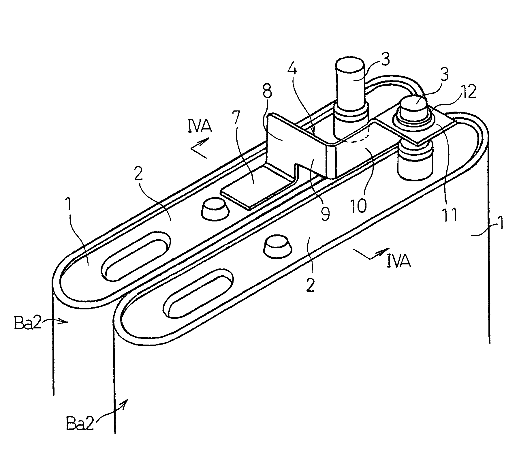
[0028]Preferred embodiments of the present invention will be hereinafter described with reference to the drawings. FIG. 1 is a perspective view illustrating relevant parts of the battery pack according to one embodiment of the present invention. Flat prismatic batteries Ba2 with a negative terminal 3 protruding from the sealing plate 2 are arranged face to face and electrically connected to each other with a connector 4.

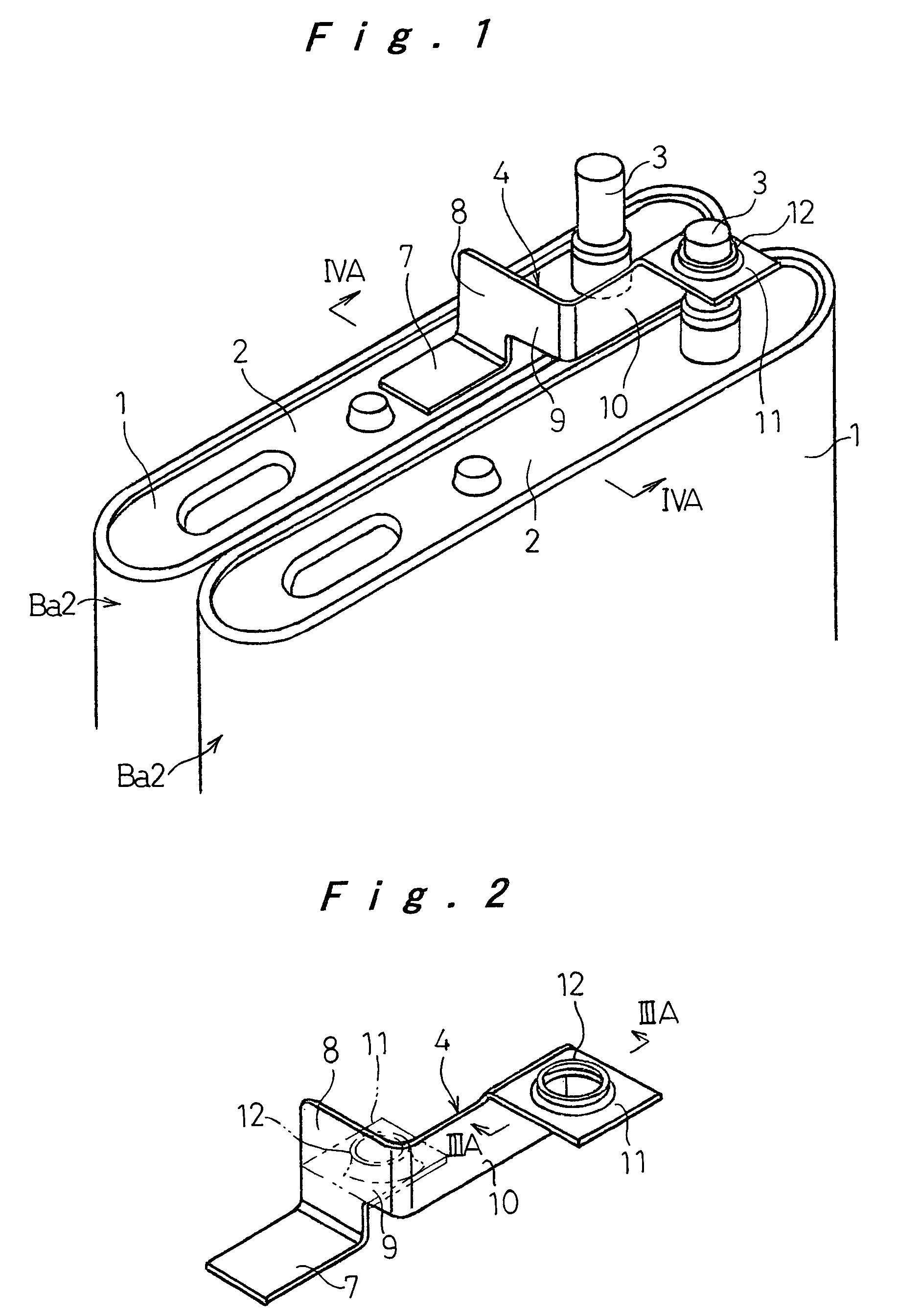
[0029]First, the connector 4 is described with reference to the perspective view of FIG. 2. The connector 4 includes: a flat part 7 welded on the sealing plate 2 of one of the two adjacent prismatic batteries Ba2, the sealing plate 2 serving as the positive electrode of the battery together with the battery case 1; an upright part 8 that is formed by bending one end of the flat part 7 at right angles; a linkage part 9 extending from substantially the upper half of the upright part 8 to one side; a connection part 10 that is formed by bending one end of the linkage pa...


PUM

PropertyMeasurementUnit
heightaaaaaaaaaa
right anglesaaaaaaaaaa
thicknessaaaaaaaaaa

Abstract

A battery pack is made up of a plurality of flat prismatic batteries arranged face to face, each battery having one electrode terminal protruding from one end face in the height direction of the battery case and this end face or a side face of the battery serving as the other electrode terminal. The connector for electrically connecting adjacent prismatic batteries includes a flat part that is welded to one electrode terminal of one prismatic battery of the adjacent prismatic batteries, and a cylindrical part that is fitted onto and welded to the other electrode terminal of the other prismatic battery. The cylindrical part is formed in an attachment part that extends from the flat part through an upright part in the direction in which the batteries are aligned. The connector enables reliable electrical connection of the prismatic batteries despite possible variation in height of the electrode terminals.

Description

[0001]The present disclosure relates to subject matter contained in priority Japanese Patent Application No. 2005-347816 filled on Dec. 1, 2005, the contents of which is herein expressly incorporated by reference in its entirety.BACKGROUND OF THE INVENTION[0002]1. Field of the Invention[0003]The present invention relates to a battery pack made up of two or more prismatic batteries electrically connected together.[0004]2. Description of the Related Art[0005]Battery assembly, more commonly known as a “battery module” or “battery pack”, is made up of two or more batteries that are connected in series to output a predetermined voltage, and used for the power source of cordless devices such as mobile phones and electric tools, or of hybrid vehicles. With the downsizing of electric devices, volume-efficient prismatic batteries are increasingly used. One problem with the battery pack of prismatic batteries is that because the batteries are arranged in face-to-face relationship, the termina...

Claims


Application Information

Patent Timeline
Patent Type & Authority Patents(United States)
IPC IPC(8): H01M2/24H01M50/528H01M50/503H01M50/529H01M50/51H01M50/516H01M50/522H01M50/553
CPCY02E60/10H01M50/522H01M50/516H01M50/51H01M50/553H01M50/503H01M10/46H01M50/528H01M50/543H01M50/502
Inventor NAGATANI, MASATOMOHIRAKAWA, YASUSHI
Owner PANASONIC CORP
Why Eureka
Try Eureka