Method and system for providing optical proximity correction for structures such as a PMR nose

Inactive Publication Date: 2010-06-15
WESTERN DIGITAL TECH INC +1
View PDF14 Cites 152 Cited by
  • Summary
  • Abstract
  • Description
  • Claims
  • Application Information

AI Technical Summary

Benefits of technology

[0005]According to the method and system disclosed herein, the present invention provides a resist m

Problems solved by technology

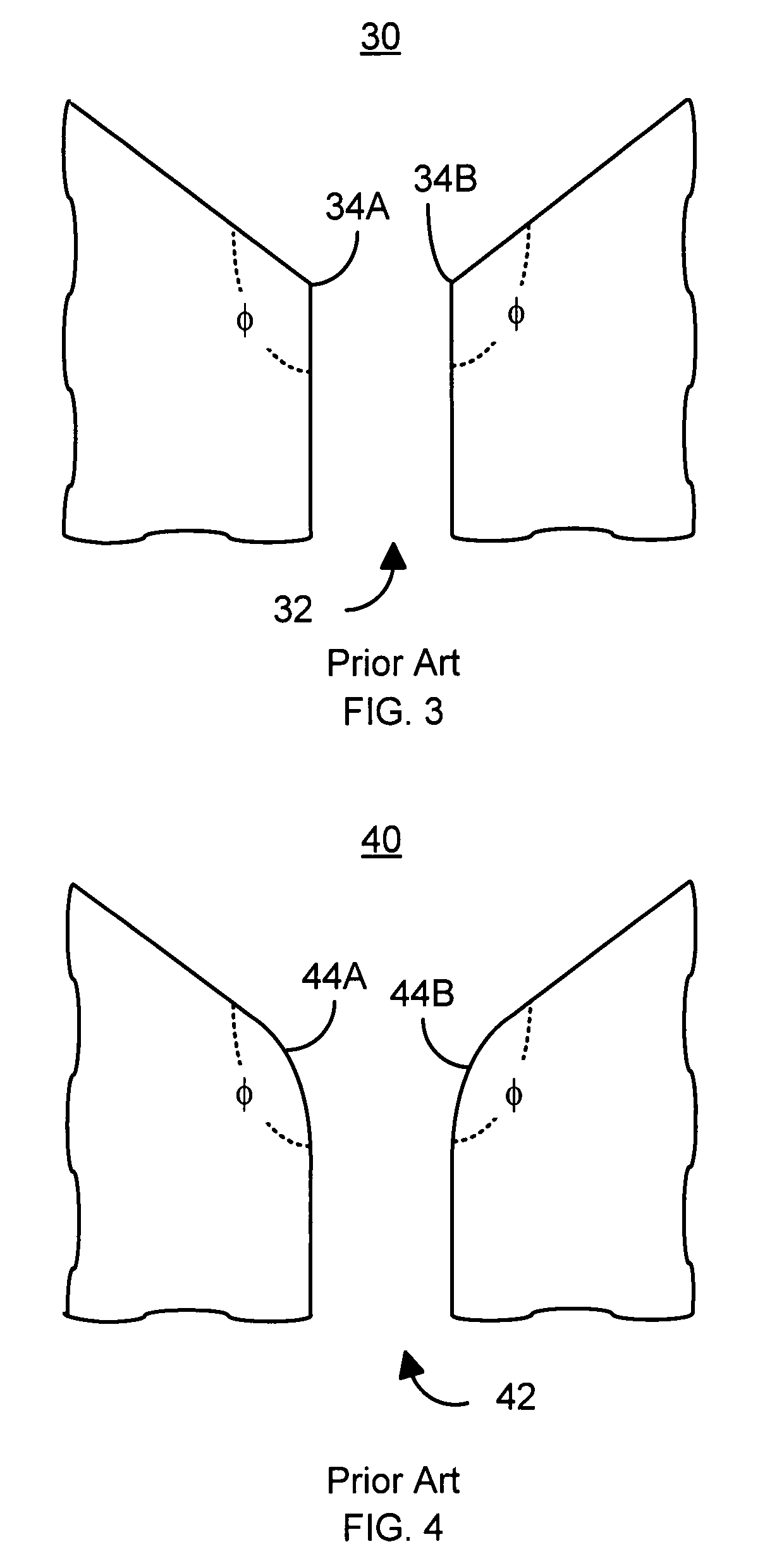
In particular, the shape of the nose 19 may not be well controlled.
Even though the desired obtuse angle, φ, may be a

Method used


Image

  • Method and system for providing optical proximity correction for structures such as a PMR nose
  • Method and system for providing optical proximity correction for structures such as a PMR nose
  • Method and system for providing optical proximity correction for structures such as a PMR nose

Examples


Embodiment Construction

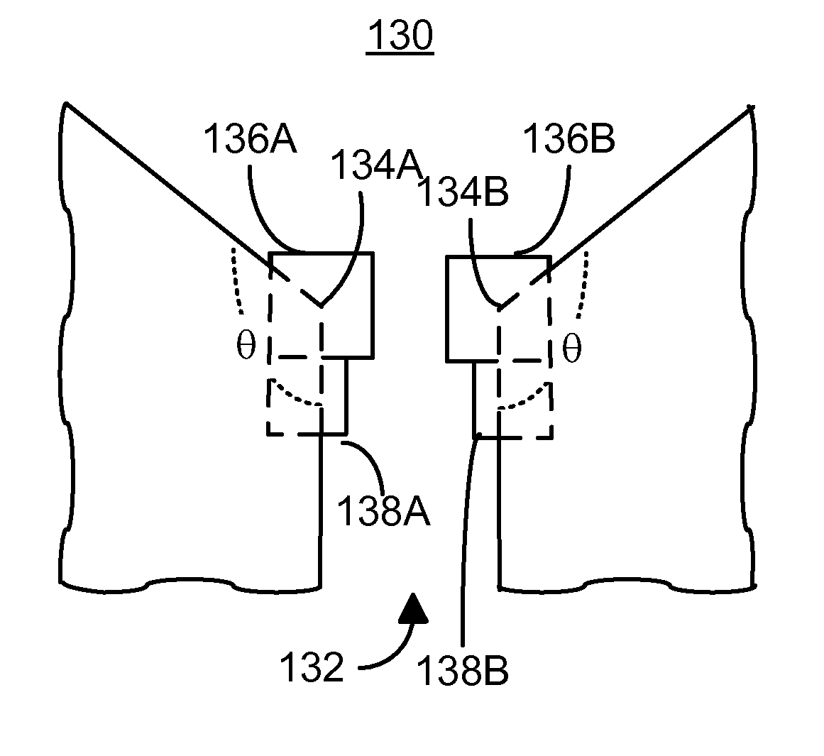
[0016]FIG. 5 is a flow chart depicting an exemplary embodiment of a method 100 for forming structures having an obtuse angle, such as a PMR pole. A mask is provided, via step 102. The mask includes a corner that corresponds to an angle of between ninety and one hundred eighty degrees. Thus, the mask includes an obtuse angle. In addition, the mask includes at least one rectangular serif. At least one of the serif(s) resides at the corner. The pattern in the mask is optically transferred from the mask to a resist layer to provide a resist mask, via step 104. A portion of the magnetic recording transducer is formed using the resist mask, via step 106. For example, A PMR pole may be formed using the resist mask in step 106. In such an embodiment, the resist mask may include a trench that is defined using the mask. The trench may be used in forming the PMR pole. Alternatively, the mask and the resist mask may be used in forming other structures, such as conductive lines.

[0017]Because of ...


PUM


Abstract

A mask for transferring a pattern for portion of a magnetic recording transducer is disclosed. The masks includes one corner corresponding to an angle of more than ninety degrees and less than one hundred eighty degrees. The mask also includes at least one rectangular serif residing at the corner.

Description

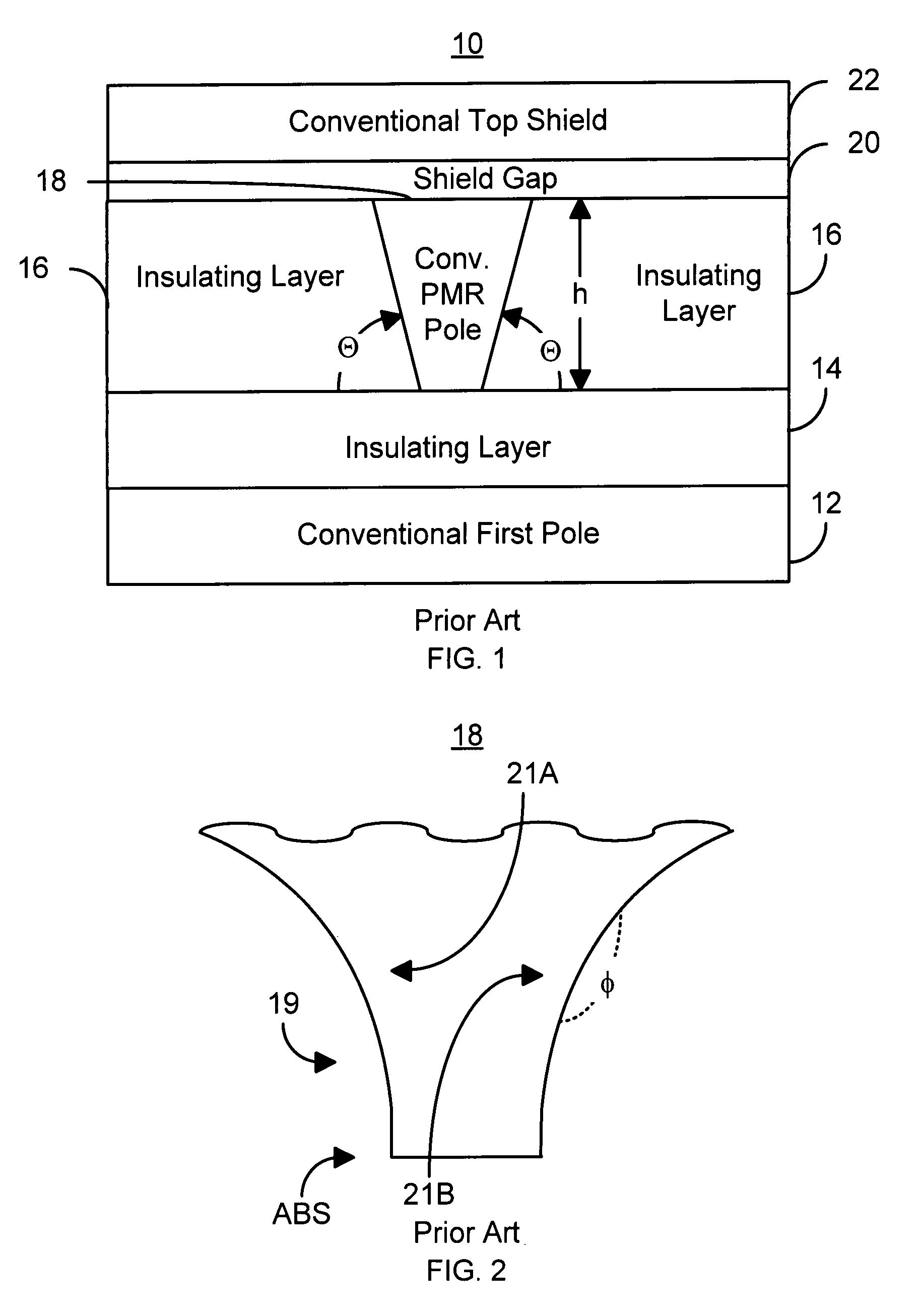
BACKGROUND OF THE INVENTION[0001]FIG. 1 depicts air-bearing surface (ABS) view of a conventional perpendicular magnetic recording (PMR) transducer 10 used in recording a PMR media (not shown). The conventional PMR transducer 10 is typically used as a write head in a merged head including the conventional PMR transducer 10 and a read head. The conventional PMR transducer 10 includes a conventional first pole (P1) 12, insulator 14, insulator 16, a conventional PMR pole (main pole) 18, write gap 20, and shield 22. The PMR pole 18 has a negative angle, Θ. Thus, the top of the conventional PMR pole 18 is wider than the bottom of the PMR pole 18. FIG. 2 depicts a top view of a portion of the conventional PMR pole 18. Near the ABS, the conventional PMR pole 18 terminates in a nose 19. The conventional PMR pole 18 thus flares outward from the nose 19 at a flare angle, φ, forming corners 21A and 21B. The flare angle, φ, is typically desired to be approximately one hundred and fifty degrees.[...

Claims


Application Information

Patent Timeline
IPC IPC(8): G03F1/00
CPCG11B5/3163G11B5/3116G11B5/1278G03F1/36
Inventor WANG, YIZHONGSUN, HAIYUAN, HONGPINGYU, WINNIE
Owner WESTERN DIGITAL TECH INC
Why Eureka
Try Eureka