Optical safety element and system for visualising hidden information

Inactive Publication Date: 2010-06-15
OVD KINEGRAM AG
View PDF31 Cites 14 Cited by
  • Summary
  • Abstract
  • Description
  • Claims
  • Application Information

AI Technical Summary

Benefits of technology

[0029]Further improvements in the degree of safeguard against forgery can be achieved if, instead of a binary verification grating, a verification grating is used which is defined by a non-binary transmission function, for ex

Problems solved by technology

They too cannot be imitated by means of conventional holographic methods.
Accor

Method used


Image

  • Optical safety element and system for visualising hidden information
  • Optical safety element and system for visualising hidden information
  • Optical safety element and system for visualising hidden information

Examples


Embodiment Construction

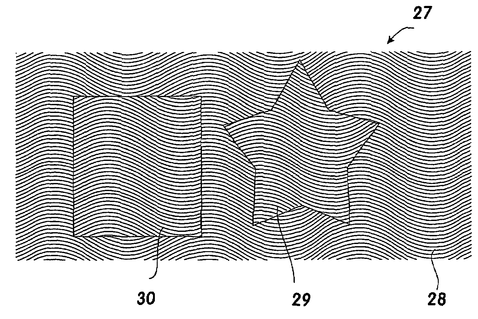
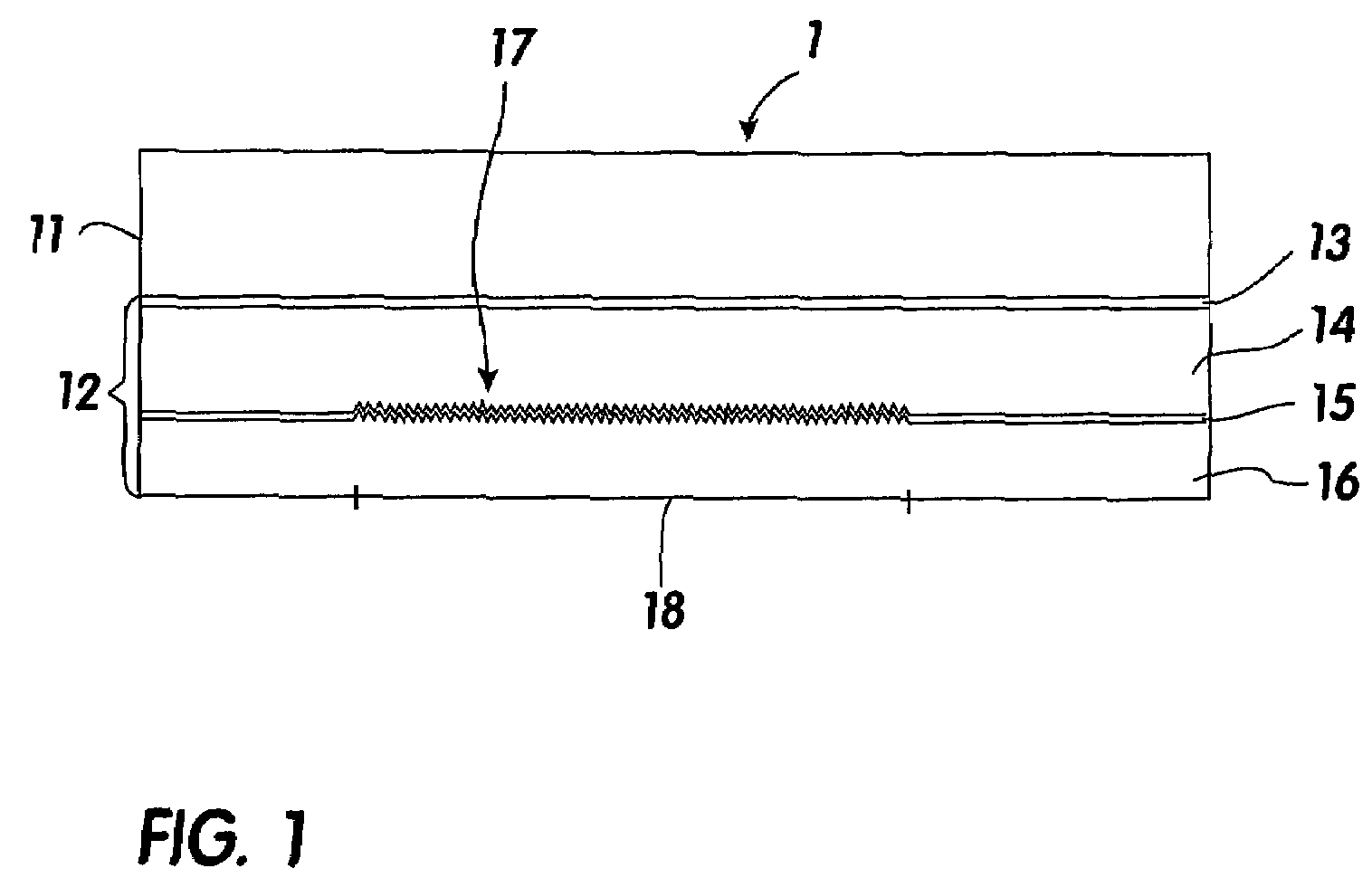
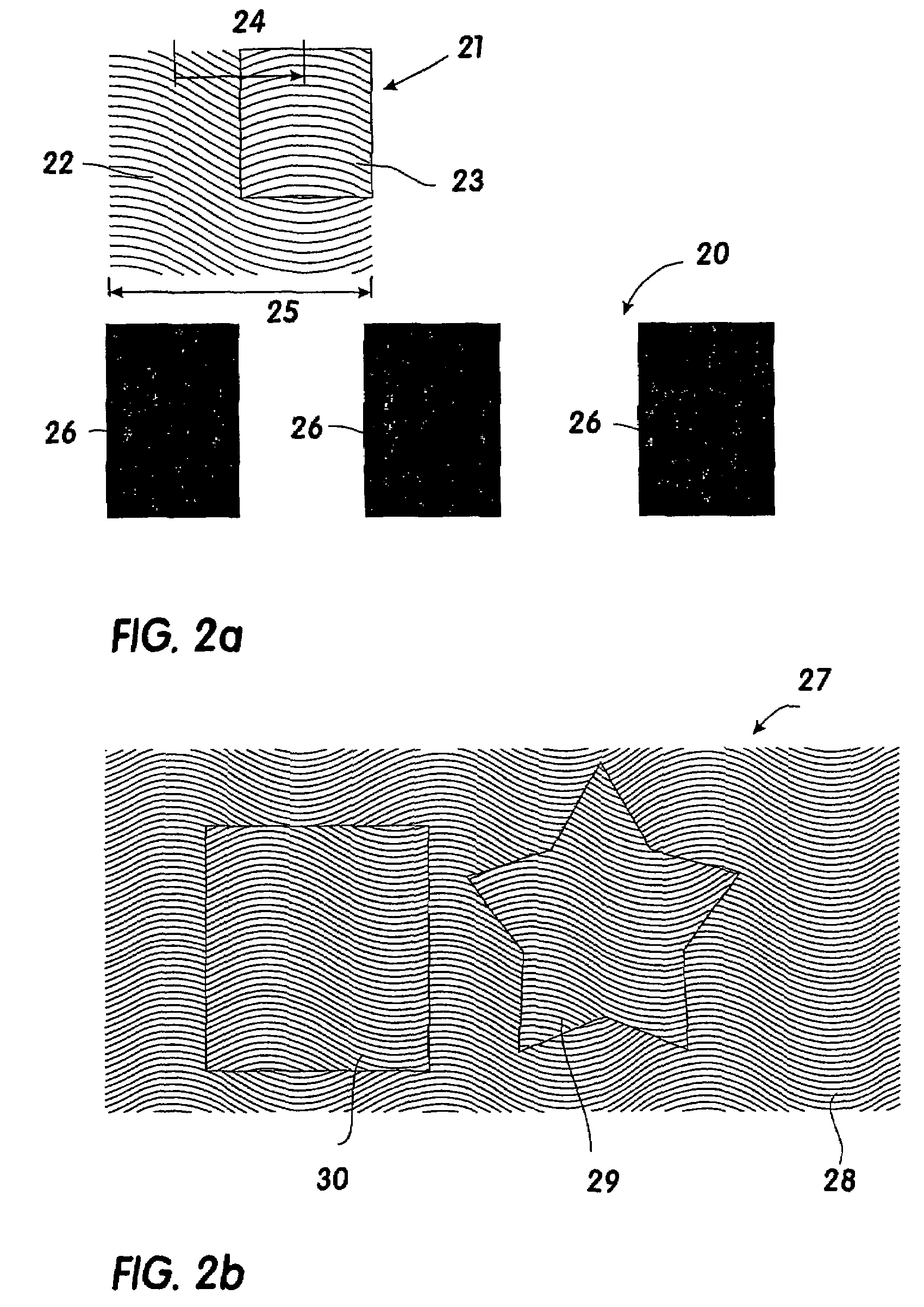
[0045]FIG. 1 shows a stamping film 1 which has a carrier film 11 and a transfer layer portion 12 serving as an optical security element. The transfer layer portion 12 has a release and / or protective lacquer layer 13, a replication layer 14, a reflection layer 15 and an adhesive layer 16. The carrier layer 21 comprises for example a polyester film of a thickness of 12 μm to 50 μm. Applied to the carrier film is the release and / or protective lacquer layer 13, in a thickness of 0.3 to 1.2 μm, as well as the replication layer 14. It would also be possible in that respect to dispense with the release and / or protective lacquer layer 13.

[0046]The replication layer 14 is preferably a transparent thermoplastic material which is applied for example by means of a printing process to the film body formed by the carrier film 11 and the protective lacquer and / or release layer 13. After drying a relief structure 17 is replicated into the replication layer in the region 18 by means of a stamping to...


PUM


Abstract

The invention concerns an optical security element and a system for visualising items of concealed information comprising such an optical security element. The optical security element has a substrate layer in which a relief structure defined by relief parameters, in particular relief shape, relief depth, spatial frequency and azimuth angle, is shaped in the surface region defined by an X-axis and a Y-axis, for producing an optically perceptible effect. One or more of the relief parameters defining the relief structure are varied in the surface region in accordance with a parameter variation function. The surface region is divided into one or more pattern regions and a background region. One or more of the relief parameters defining the relief structure are varied in the one or more pattern regions in accordance with a parameter variation function which is phase-displaced in relation to the parameter variation function of the background region. There is further provided a verification element which has a verification grating which is defined by a periodic transmission function and whose period corresponds to the period of the parameter variation function.

Description

CROSS-REFERENCE TO RELATED APPLICATIONS[0001]This application is a National Phase application of International Application No. PCT / EP2004 / 006466 filed Jun. 16, 2004, which claims priority based on German Patent Application No. 103 28 759.0, filed Jun. 25, 2003, which are both incorporated herein by reference.BACKGROUND OF THE INVENTION[0002]The invention relates to an optical security element having a substrate layer in which a relief structure defined by relief parameters, in particular relief shape, relief depth, spatial frequency and azimuth angle, is shaped out in a surface region defined by an X-axis and a Y-axis, for producing an optically perceptible effect, and a system for visualising items of concealed information with such an optical security element.[0003]The ever improving photocopying technology and the ongoing development of electronic scanning and printing apparatuses mean that there is an increasing need for optical security elements which are as forgery-proof as po...

Claims


Application Information

Patent Timeline
IPC IPC(8): G02B5/18B42D15/00B42D15/10B44F1/12G02BG02B27/44G06K19/06
CPCG02B5/1866G02B5/1819B42D25/324B42D25/342G06K19/06G02B27/44
Inventor SCHILLING, ANDREASTOMPKIN, WAYNE ROBERTSTAUB, RENE
Owner OVD KINEGRAM AG
Why Eureka
Try Eureka