Method and apparatus for thermal management of computer memory modules

a technology of computer memory modules and thermal management equipment, which is applied in the direction of electrical apparatus casings/cabinets/drawers, instruments, and semiconductor/solid-state device details, etc., can solve the problems of high power consumption, high power draw, and increased power consumption of open memory pages, so as to promote thermal exchange, improve memory performance, and promote turbulent air flow.

Active Publication Date: 2010-06-15
KIOXIA CORP
View PDF15 Cites 52 Cited by
  • Summary
  • Abstract
  • Description
  • Claims
  • Application Information

AI Technical Summary

Benefits of technology

[0011]When mounted on an operating memory module, a temperature differential is created between the interior of the heat spreader heated by the memory module and the exterior of the heat spreader, causing natural air convection to occur through the perforations particularly if the heat spreader is mounted on top of the memory module so that its planar interior region is substantially horizontal. The perforations also promote turbulent air flow that further promotes thermal exchange between the heat spreader and the environment surrounding the heat spreader, in contrast to laminar air flow that typically occurs across surfaces of conventional heat spreaders. As a result, the heat spreader and method of this invention promote improved memory performance, stability, and longevity, without the costs associated with other cooling techniques, such as water-cooled memory cooling equipment.

Problems solved by technology

As a rule of thumb, power consumption of any integrated circuit increases in a linear fashion with the clock frequency and, therefore, the migration to higher memory core frequencies necessarily results in higher power draw.
Likewise, the increased power consumption of open memory pages is well documented.
However, a major drawback of such a configuration is that the heat spreader encapsulates the modules and traps the air space between the components.
The issue of heat trapping is especially of concern in the case of registered modules where a high speed clock chip or phase lock loop (PLL) chip and registers are added, either of which consumes constant power at a rate higher than that of the average memory IC.
This has led to either overheating of the PLL and heating of the memory chips by the PLL.
While effective, fans incur an additional and undesirable cost.
Other proposed solutions include the use of water-cooled memory modules that are more efficient, but are also more expensive to implement than fan cooling.

Method used


Image

  • Method and apparatus for thermal management of computer memory modules
  • Method and apparatus for thermal management of computer memory modules
  • Method and apparatus for thermal management of computer memory modules

Examples


Embodiment Construction

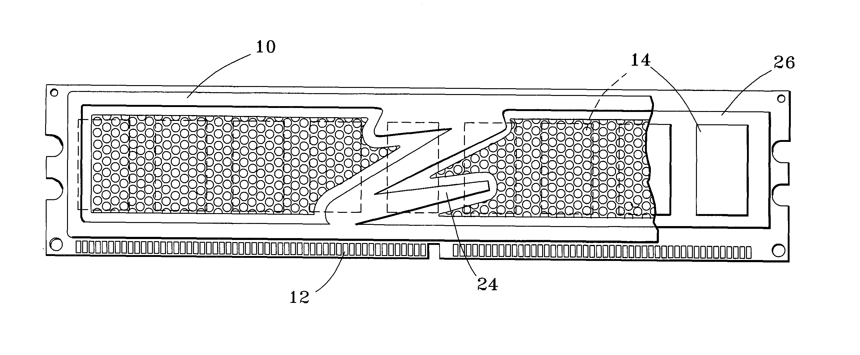
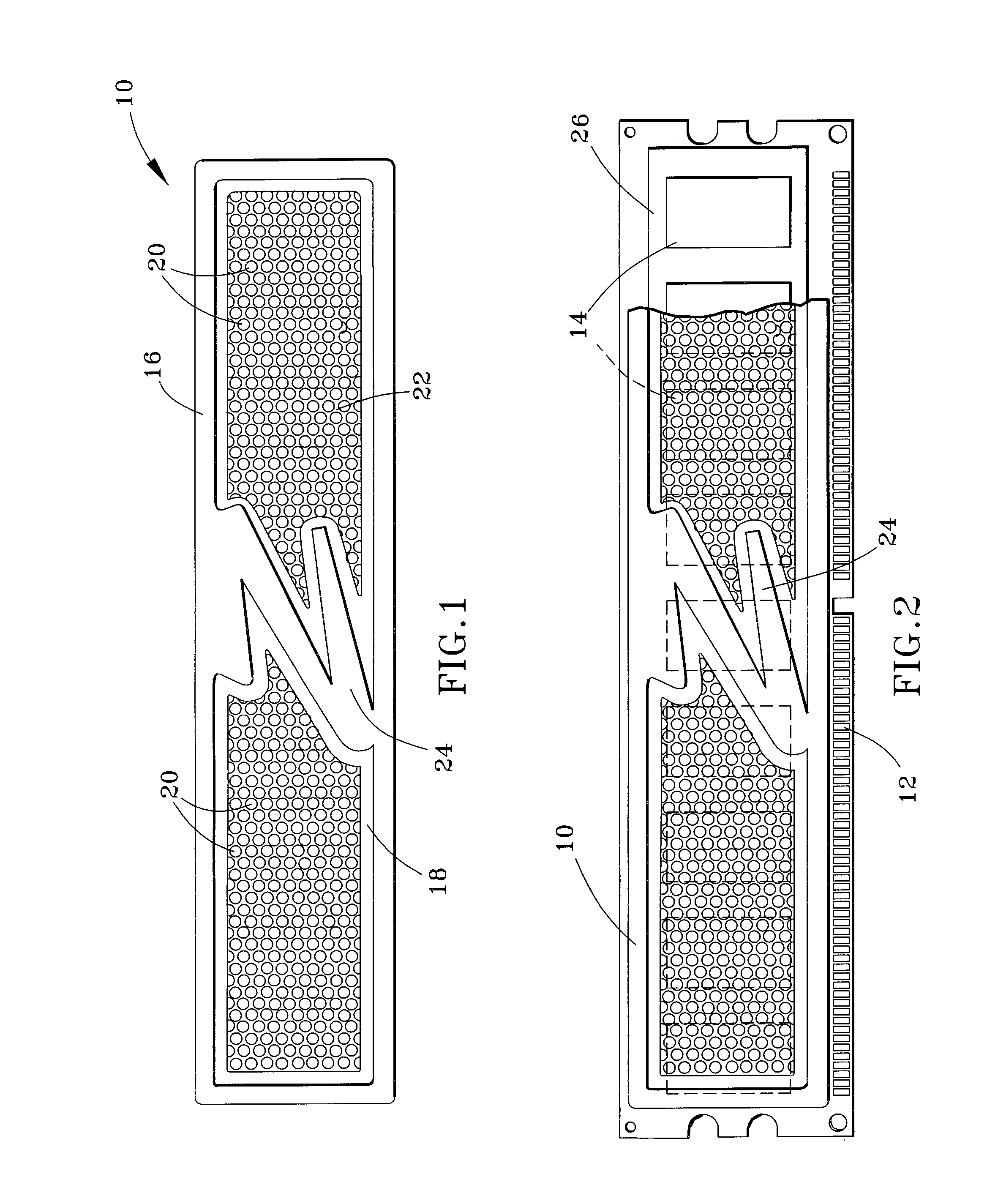
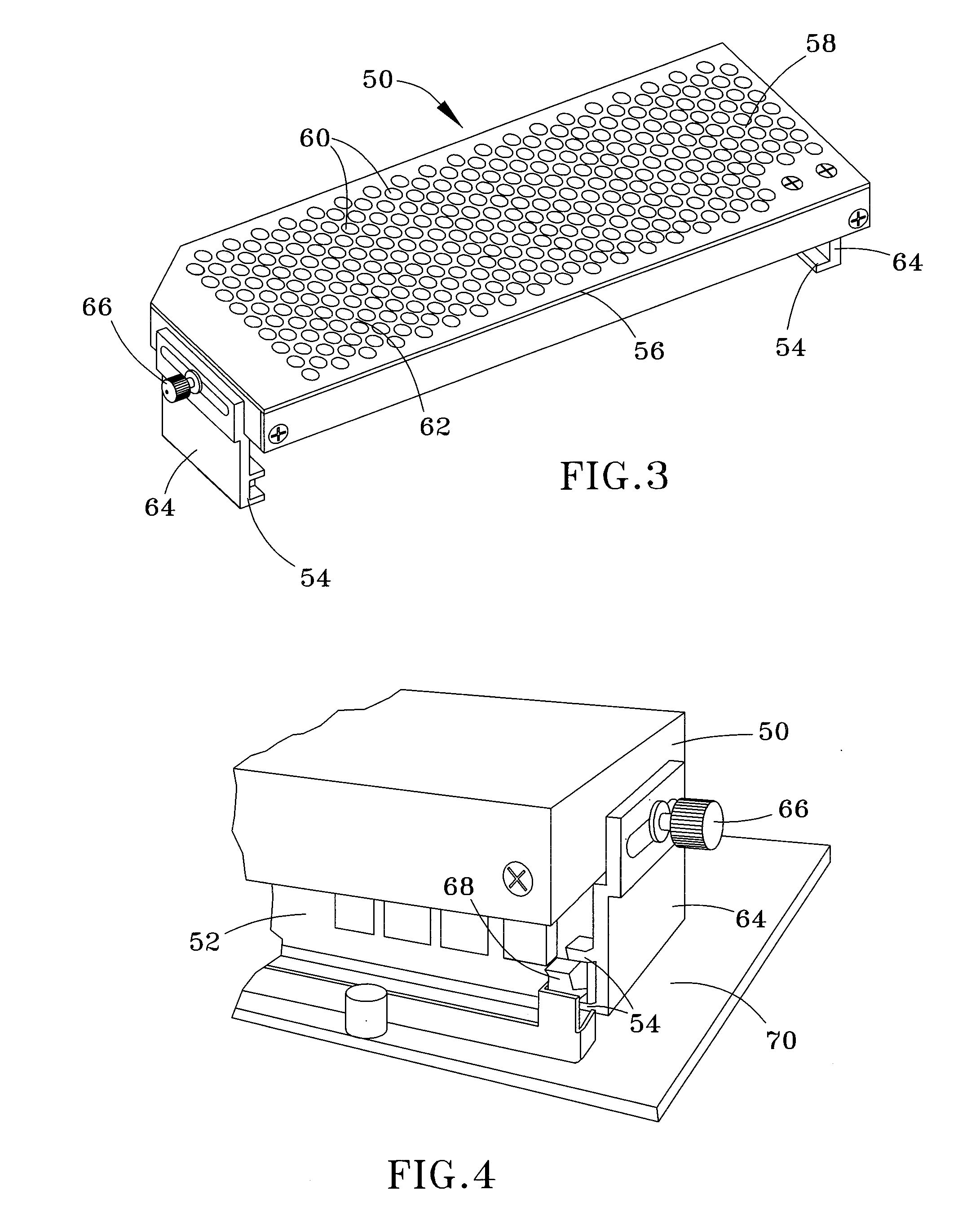
[0017]FIGS. 1 through 4 represent perforated heat spreaders 10 and 50 for use with computer memory modules, such as the memory module 12 represented in FIG. 2 as comprising a number of memory chips 14. As represented in FIGS. 1 through 4, the heat spreaders 10 and 50 have generally rectangular shapes, which as evident from FIG. 2 approximately coincides with the peripheral shape of the memory module 12 with which the heat spreader 10 is used. Preferred materials for the heat spreaders 10 and 50 include aluminum, copper, and other metal and metal alloy materials commonly used as heat sinks and conductors for thermal management applications, though it is foreseeable that other materials with reasonably good thermal conduction could also be used.

[0018]The outline of the heat spreader 10 of FIGS. 1 and 2 is defined by a frame 16 that surrounds an interior region 18 of the heat spreader 10, in which a number of perforations 20 are formed (e.g., by stamping, molding, etc.) to extend throu...


PUM


Abstract

A heat spreader and method for thermal management of a computer memory module by promoting natural convection cooling of the memory module. The heat spreader includes a frame surrounding a planar body adapted to be mounted to a memory module of a computer, and a grid defined in the planar body by a plurality of uniformly distributed perforations. The perforations extend through the planar body to allow natural convention between an interior space beneath the planar body and an exterior space above the planar body.

Description

CROSS REFERENCE TO RELATED APPLICATIONS[0001]This application claims the benefit of U.S. Provisional Application No. 60 / 766,292, filed Jan. 9, 2006, the contents of which are incorporated herein by reference.BACKGROUND OF THE INVENTION[0002]The present invention relates to thermal management equipment and methods for computer memory modules, and more particular to a heat spreader that can be assembled with a memory module to promote natural convection cooling of the module.[0003]Memory bandwidth requirements have steadily increased as a countermeasure against data starvation of central processors of personal computers. A number of different strategies have been employed to provide better data throughput to and from the system memory pool. The three most important measures have been to increase the memory clock frequency, increase the data rate, and increase the number of physical banks to allow for more pages that can be held open.[0004]As a rule of thumb, power consumption of any i...

Claims


Application Information

Patent Timeline
Patent Type & Authority Patents(United States)
IPC IPC(8): H05K7/20G06F1/20
CPCG06F1/206
Inventor SCHUETTE, FRANZ MICHAELPETERSEN, RYAN M.NELSON, ERIC L.SETHI, BHULINDER
Owner KIOXIA CORP
Why Eureka
Try Eureka