Highly aligned x-ray optic and source assembly for precision x-ray analysis applications

a source assembly and x-ray technology, applied in the field of x-ray analysis systems, can solve the problems of increasing the power supply of expensive, high-power tubes or other sources, increasing the cost and complexity of fielded systems, and the need to align disparate components

Inactive Publication Date: 2010-06-15
X-RAY OPTICAL SYSTEM INC
View PDF3 Cites 32 Cited by
  • Summary
  • Abstract
  • Description
  • Claims
  • Application Information

AI Technical Summary

Problems solved by technology

In the past, obtaining an illumination spot size of sufficient intensity on a small sample area typically necessitated increasing the power supplied to expensive, high-powered tubes or other sources.
Another issue, which particularly affects volume manufacturing, is the need to align disparate components which may be purchased from different vendors.
These types of systems are necessary and valuable for certain applications, but can also increase the cost and complexity of fielded systems.

Method used


Image

  • Highly aligned x-ray optic and source assembly for precision x-ray analysis applications
  • Highly aligned x-ray optic and source assembly for precision x-ray analysis applications
  • Highly aligned x-ray optic and source assembly for precision x-ray analysis applications

Examples


Embodiment Construction

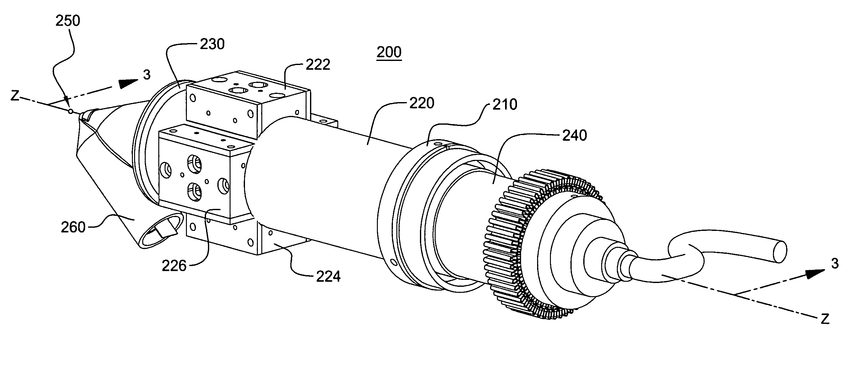
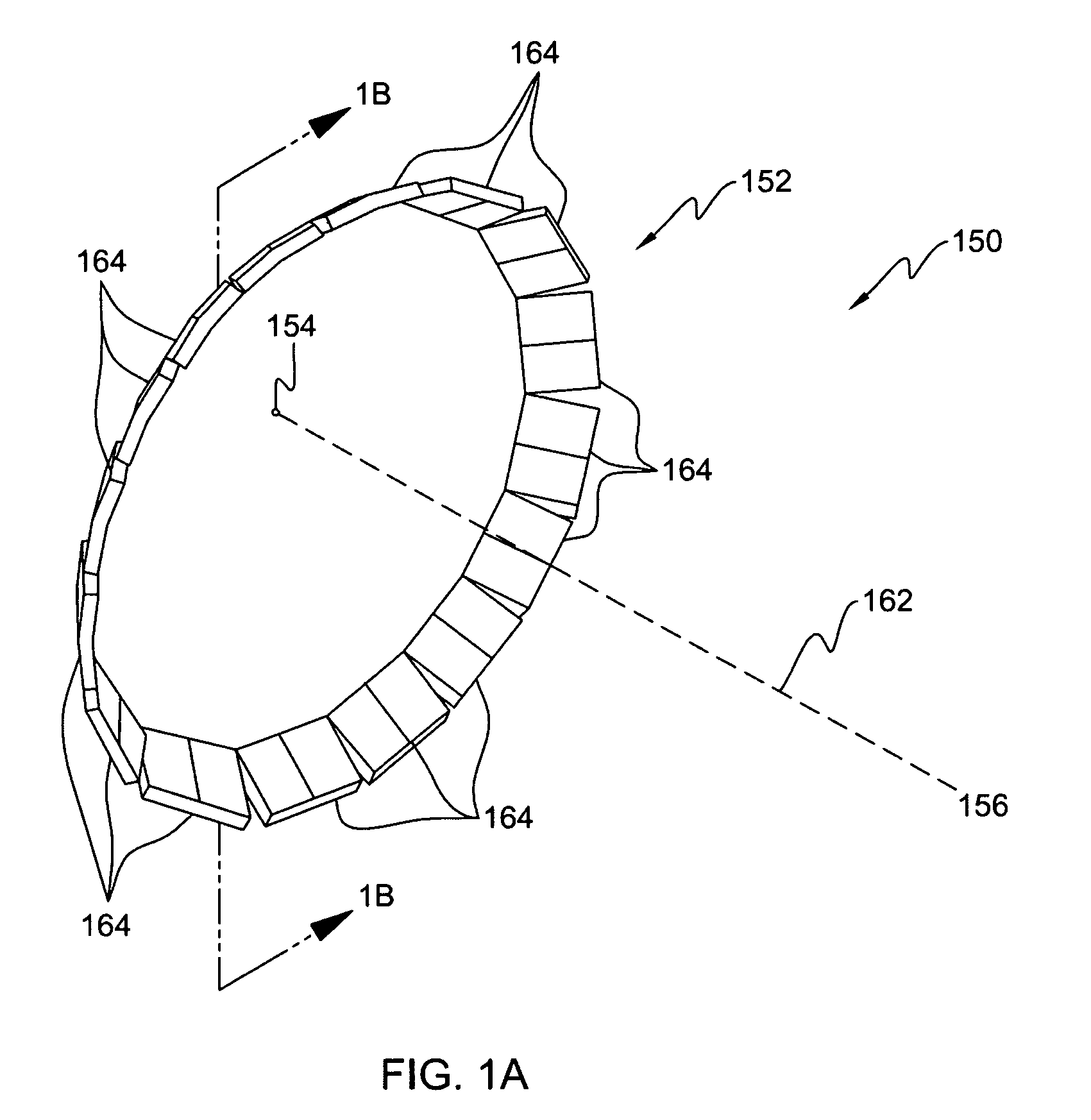
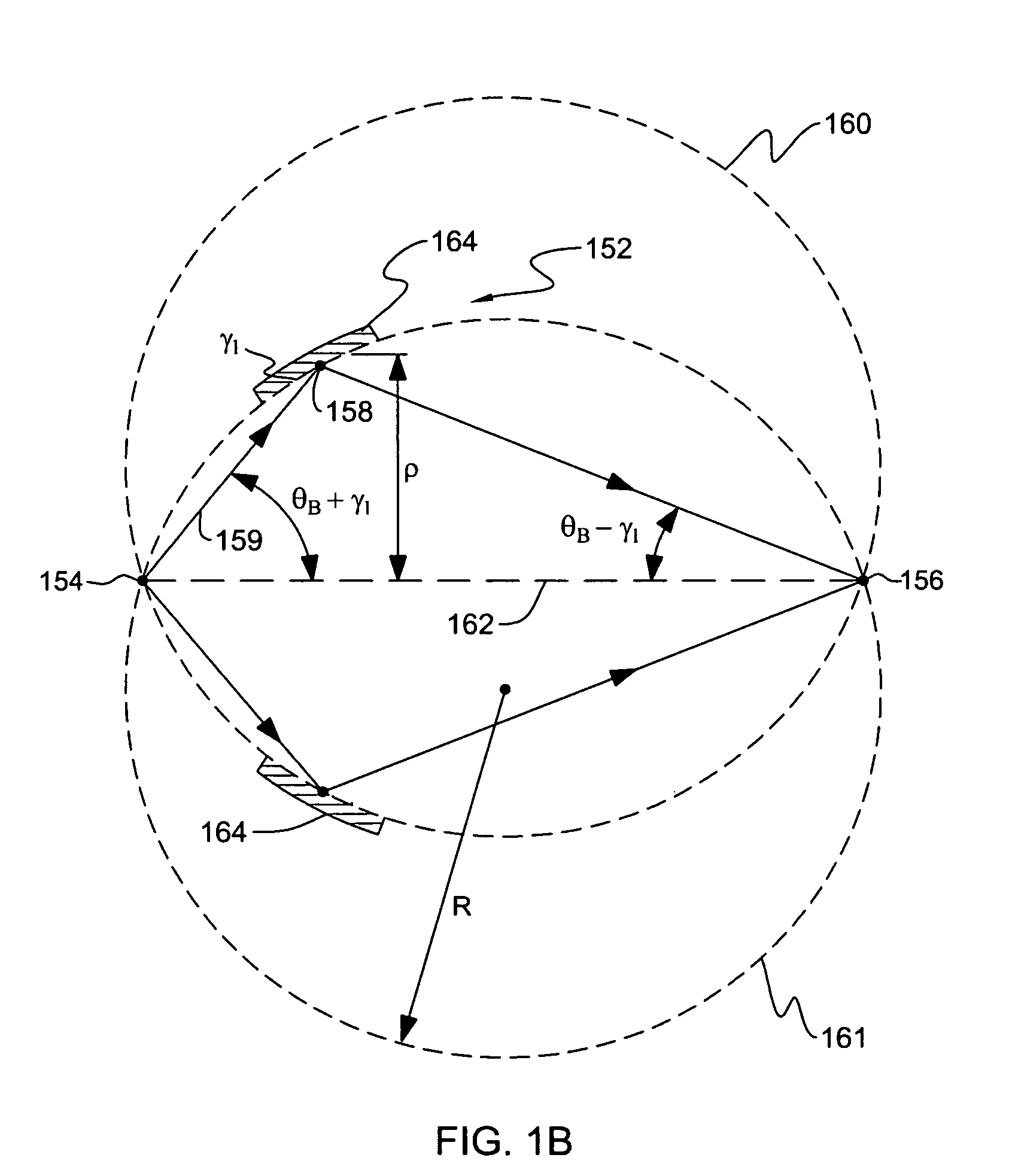
[0025]In accordance with the present invention, FIGS. 2-6 depict in various views (using like numerals to refer to like elements) a highly-aligned x-ray optic and source assembly 200. The assembly includes a first section 210, second section 220, and third section 230, which together align an x-ray tube 240 to a sample spot 250, along a central transmission axis Z. Also aligned along this axis are multiple optic carriage assemblies 222, 224, 226 which hold exemplary monochromating optics also requiring alignment to transmission axis Z (as discussed above with respect to FIGS. 1a-b).

[0026]First housing section 210 may include adjustable tube-mounting features 212, 214 about its perimeter for adjustably mounting tube 240 thereby ensuring centering of tube x-ray spot 242 centrally along a central axis of section 210 (not shown). As discussed below, further attachment of assembly sections 210, 220, and 230 will ensure that each respective section's axis (not shown) is ultimately aligned...


PUM


Abstract

An x-ray analysis apparatus for illuminating a sample spot with an x-ray beam. An x-ray tube is provided having a source spot from which a diverging x-ray beam is produced, the source spot requiring alignment along a transmission axis passing through the sample spot. A first housing section is provided, to which the x-ray tube is attached, including mounting features for adjustably mounting the x-ray tube therein such that the source spot coincides with the transmission axis. A second housing section includes a second axis coinciding with the transmission axis; and at least one x-ray optic attached to the second housing section for receiving the diverging x-ray beam and directing the beam toward the sample spot. Complimentary mating surfaces may be provided to align the first and second sections, and the optics, to the transmission axis. A third housing section may also be provided, including an aperture through which the x-ray beam passes, and to which a detector may be attached.

Description

CROSS-REFERENCE TO RELATED APPLICATIONS[0001]This application claims the benefit of U.S. provisional patent application Ser. No. 61 / 033,899, filed Mar. 5, 2008, and of U.S. provisional patent application Ser. No. 61 / 039,220, filed Mar. 25, 2008, each of which is hereby incorporated herein by reference in its entirety.TECHNICAL FIELD[0002]The present invention relates generally to x-ray analysis systems, and more particularly, to x-ray source assemblies having a focused or collimated x-ray beam output(s) with enhanced alignment and manufacturability.BACKGROUND OF THE INVENTION[0003]Small, compact x-ray tubes have experienced widespread adoption in x-ray fluorescence (XRF) spectroscopy and x-ray diffraction (XRD) instruments, for a wide range of industrial and other applications. X-ray tubes conventionally emit radiation in a divergent manner. In the past, obtaining an illumination spot size of sufficient intensity on a small sample area typically necessitated increasing the power sup...

Claims


Application Information

Patent Timeline
Patent Type & Authority Patents(United States)
IPC IPC(8): G21K1/06
CPCB82Y10/00G21K1/06G21K1/062G21K2201/067G21K2201/062G21K2201/064G21K2201/061
Inventor BURDETT, JR., JOHN H.BAILEY, ADAMCHEN, ZEWUSEMKEN, R. SCOTTXIN, KAI
Owner X-RAY OPTICAL SYSTEM INC
Why Eureka
Try Eureka