Optical alignment of X-ray microanalyzers

a microanalyzer and optical alignment technology, applied in the direction of instruments, radiation beam directing means, material analysis using wave/particle radiation, etc., can solve problems such as difficulty in achieving, and achieve the effect of accurate alignment of x-ray spots

Inactive Publication Date: 2006-04-04
BRUKER TECH LTD
View PDF28 Cites 26 Cited by
  • Summary
  • Abstract
  • Description
  • Claims
  • Application Information

AI Technical Summary

Benefits of technology

[0004]X-ray microanalyzers are useful for analyzing characteristics of small features on samples, such as circuit elements deposited on semiconductor wafers. The sizes of these elements may be substantially less than 1 mm. Accurate alignment of the X-ray spot with the feature of interest is therefore important but may be difficult to achieve. In response to this need, embodiments of the present invention provide X-ray microanalyzers having an optical observation channel, which is aligned with the X-ray source and enables the X-ray spot to be precisely aligned with features of interest on the sample.

Problems solved by technology

Accurate alignment of the X-ray spot with the feature of interest is therefore important but may be difficult to achieve.

Method used


Image

  • Optical alignment of X-ray microanalyzers
  • Optical alignment of X-ray microanalyzers
  • Optical alignment of X-ray microanalyzers

Examples


Embodiment Construction

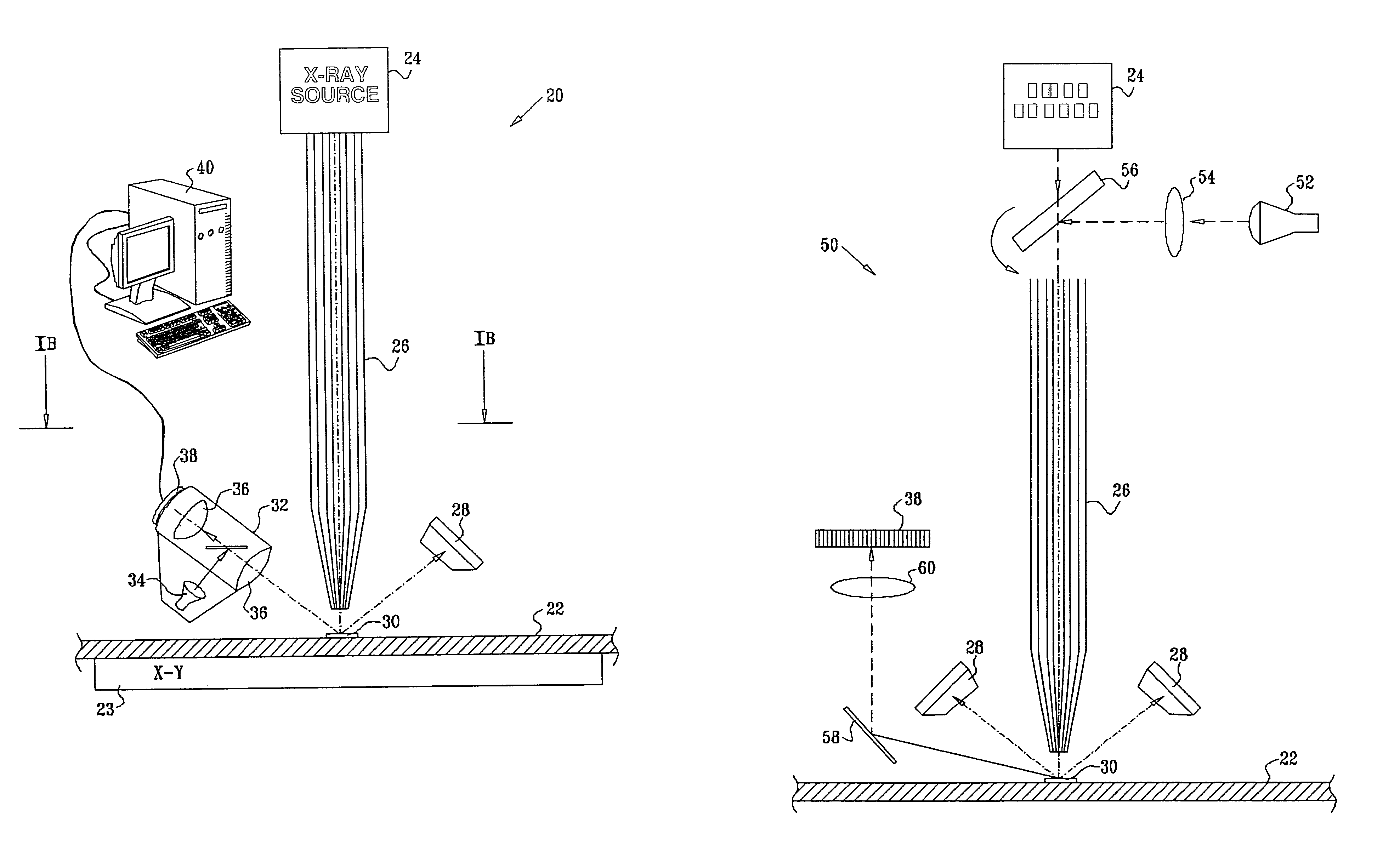
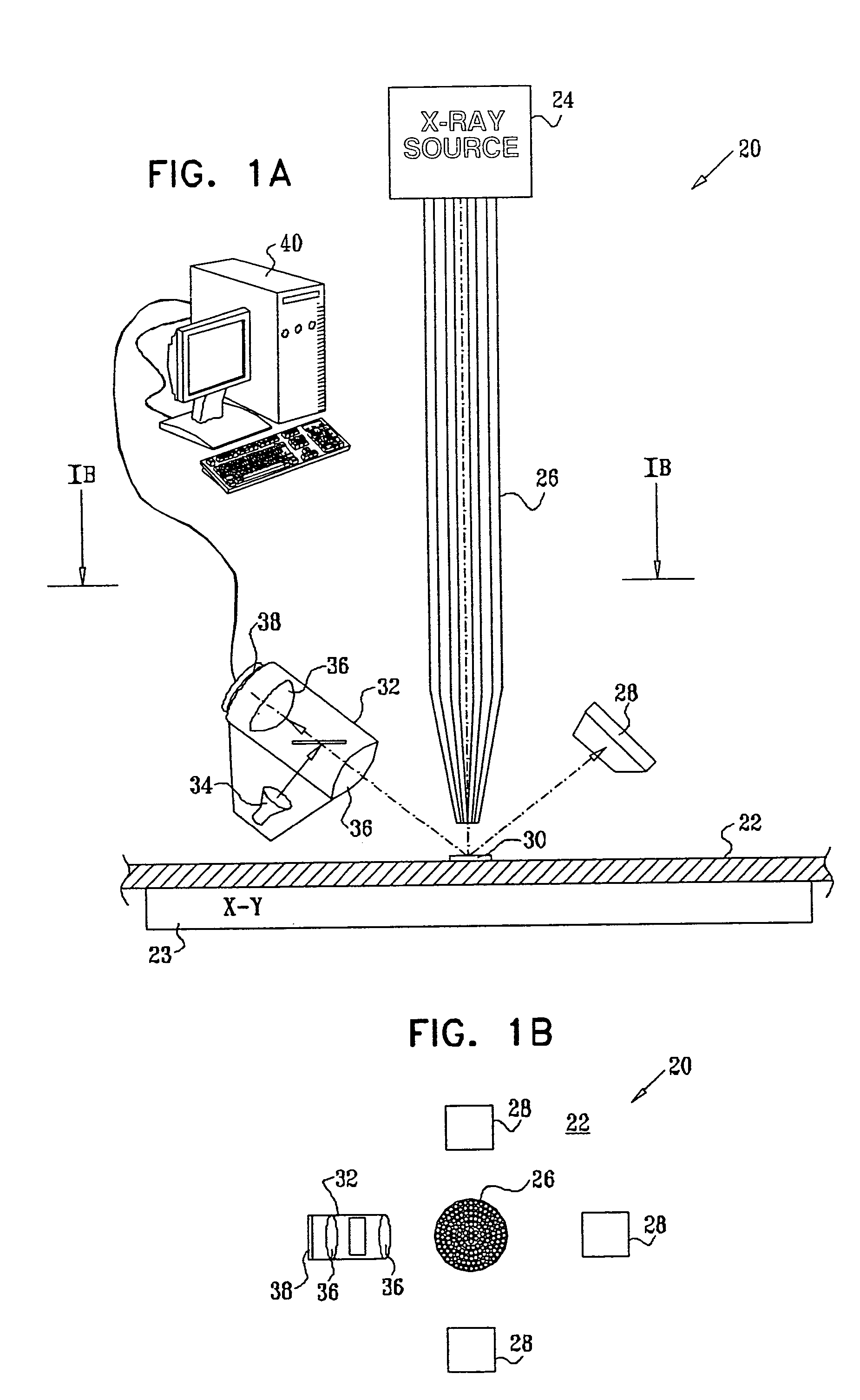
[0036]Reference is now made to FIGS. 1A and 1B, which schematically illustrate an X-ray microanalyzer 20, for analysis of a sample 22, in accordance with an embodiment of the present invention. FIG. 1A is a side view of the microanalyzer, while FIG. 1B is a sectional view, taken along a line IB—IB in FIG. 1A, looking downward toward sample 22. The sample is typically planar, such as a semiconductor wafer, and is mounted on a motion stage 23. Alternatively, the sample may be stationary, and another motion device (not shown) may be used to move the elements of the microanalyzer relative to the sample.

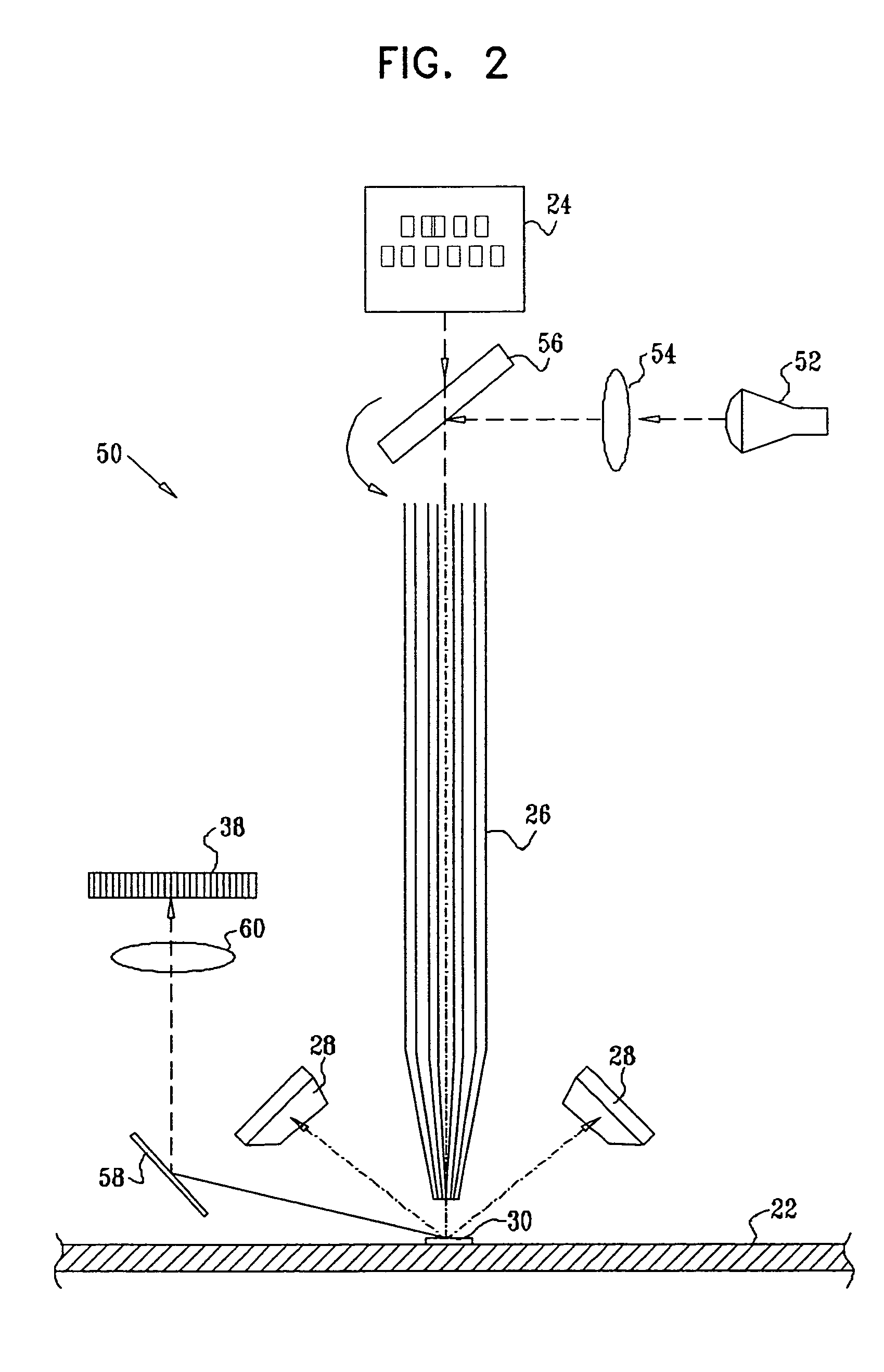
[0037]Microanalyzer 20 comprises an X-ray source 24, typically an X-ray tube, which irradiates a small spot on sample 22 with a beam of X-rays. In the exemplary embodiments shown here, a polycapillary X-ray optic 26 is used to focus the X-rays onto the sample, as described in the above-mentioned U.S. Pat. No. 6,108,398. Alternatively, X-ray optics of other types, as are known in the art, ...


PUM

PropertyMeasurementUnit
diameteraaaaaaaaaa
sizesaaaaaaaaaa
areaaaaaaaaaaa

Abstract

A method for X-ray analysis of a sample includes aligning an optical radiation source with an X-ray excitation source, so that a spot on the sample that is irradiated by an X-ray beam generated by the X-ray excitation source is illuminated with optical radiation generated by the optical radiation source. Optical radiation that is reflected from the sample is used to generate a first signal, which is indicative of an alignment of the spot on the sample. The X-ray beam is aligned, responsively to the first signal, so that the spot coincides with a target area of the sample. X-ray photons received from the spot on the sample, after aligning the X-ray beam, are used in generating a second signal that is indicative of a characteristic of the target area.

Description

FIELD OF THE INVENTION[0001]The present invention relates generally to instruments for X-ray analysis, and specifically to methods and devices for aligning such instruments to analyze a target area of a sample.BACKGROUND OF THE INVENTION[0002]X-ray microanalyzers use an X-ray beam to irradiate a small spot on a sample. The microanalyzer then detects X-rays that are emitted from the spot, by reflection, scattering or fluorescence, in order to determine properties of the sample with fine spatial resolution.[0003]For example, U.S. Pat. No. 6,108,398, whose disclosure is incorporated herein by reference, describes an X-ray microfluorescence analyzer. A sample is irradiated with X-rays through a polycapillary optic, which focuses the X-ray beam to a spot about 50 μm in diameter. Multiple X-ray detectors, such as silicon PIN diodes, are arranged in a ring, centered over the spot, in order to capture the emitted fluorescent photons over a large range of angles. The X-ray detectors produce ...

Claims


Application Information

Patent Timeline
Patent Type & Authority Patents(United States)
IPC IPC(8): G01N23/223A61B6/08G01N23/22
CPCG01N23/22
Inventor RAFAELI, TZACHIMAZOR, ISAAC
Owner BRUKER TECH LTD
Why Eureka
Try Eureka