Continuously scanning X-ray analyzer having improved readiness and accuracy

a technology of x-ray analyzer and continuous scanning, which is applied in the direction of material analysis using wave/particle radiation, material analysis by measuring secondary emission, instruments, etc., can solve the problems of inability to do analysis at each end, inability to quickly and accurately measure qualitative analysis or semi-quantitative analysis over a relatively wide range of wavelengths, and inability to perform high-precision step scan measurement. a relatively long time,

Inactive Publication Date: 2002-06-11
RIGAKU CORP
View PDF1 Cites 26 Cited by
  • Summary
  • Abstract
  • Description
  • Claims
  • Application Information

AI Technical Summary

Problems solved by technology

On the other hand, if a method which counting is not performed in the ranges of the accelerated or decelerated speed shown by `a` or `c` is taken for accurate measurement, the analyses at each end can not be done.
Accordingly, rapid and accurate measurement of qualitative analysis or semi-quantitative analysis can not be done over a relatively wide range of wavelength.
In addition, in an X-ray diffractometer for analyzing the crystalline structure of sample, in which a sample support to place of the sample to be analyzed and a detector are linked by the goniometer so that the intensity of diffracted X-rays diffracted by the sample can be measured by varying the incident angle of X-rays irradiated upon the sample, a high precision measurement carried out by the step scan requires a relatively long time.
However, accurate measurement is not possible because the counting time is not strictly constant for the fixed scanning interval.
While the foregoing description applies where the detector rotates on the spectroscopic device or the sample by the goniometer to accomplish the continuous scan, problems similar to those discussed above can be found even where a measurement unit including an X-ray source and a detector shuttles on a sample by the continuous scan.
However, it has been found difficult to strictly maintain a constant value the speed at which the measurement unit is moved by the drive means, and the moving speed of the measurement unit varies to a certain extent.
Consequently, association of the measured intensity with the particular section and, hence, association of the amount of silicon coated with the particular section tends to depart from each other and, therefore the amount of silicone coated cannot be accurately determined for each section.

Method used


Image

  • Continuously scanning X-ray analyzer having improved readiness and accuracy
  • Continuously scanning X-ray analyzer having improved readiness and accuracy
  • Continuously scanning X-ray analyzer having improved readiness and accuracy

Examples


first embodiment

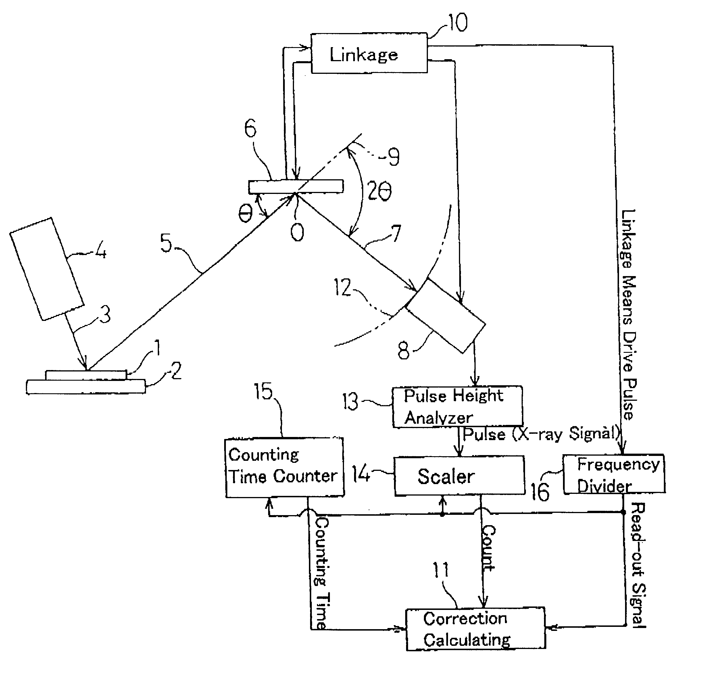
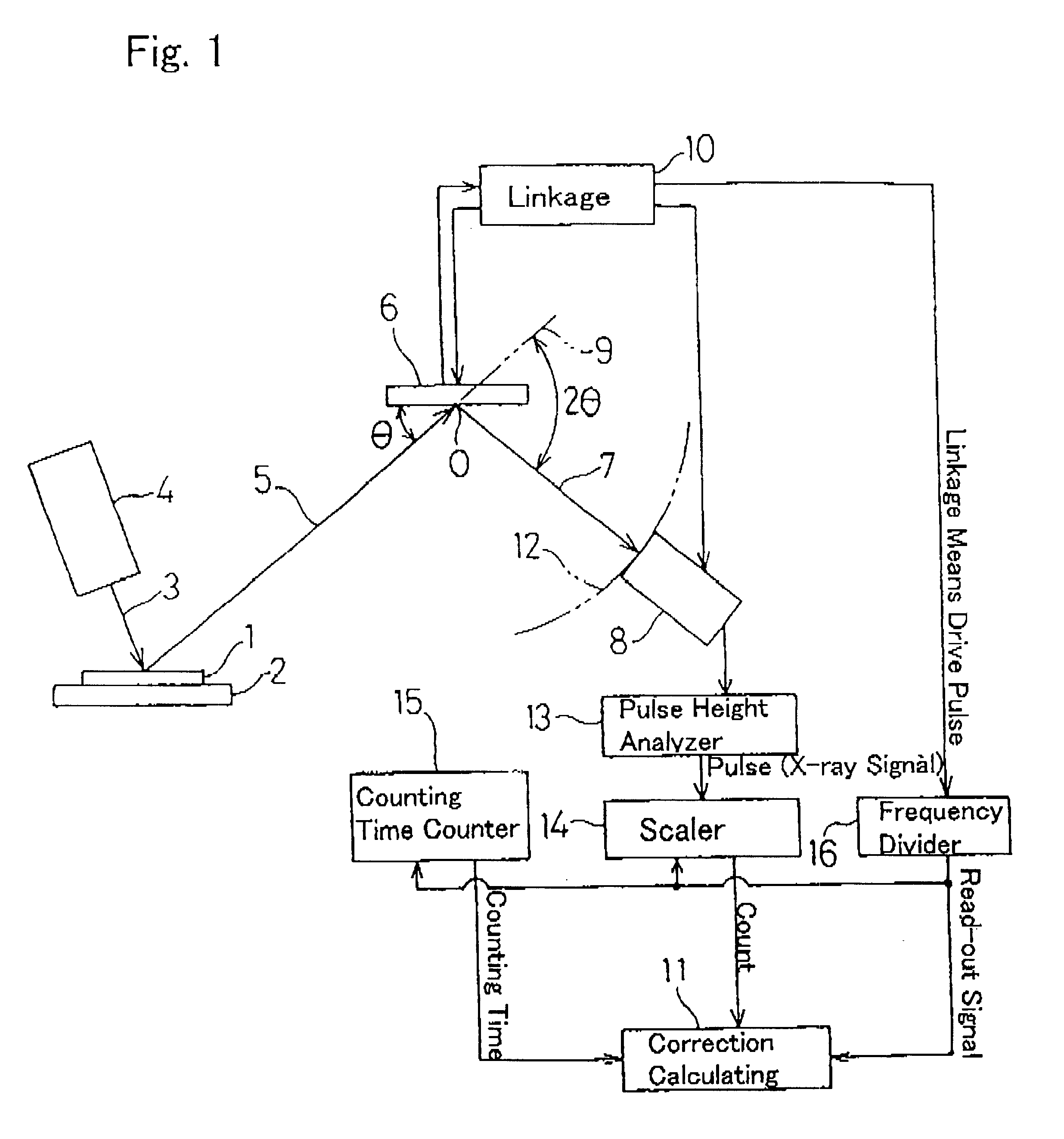
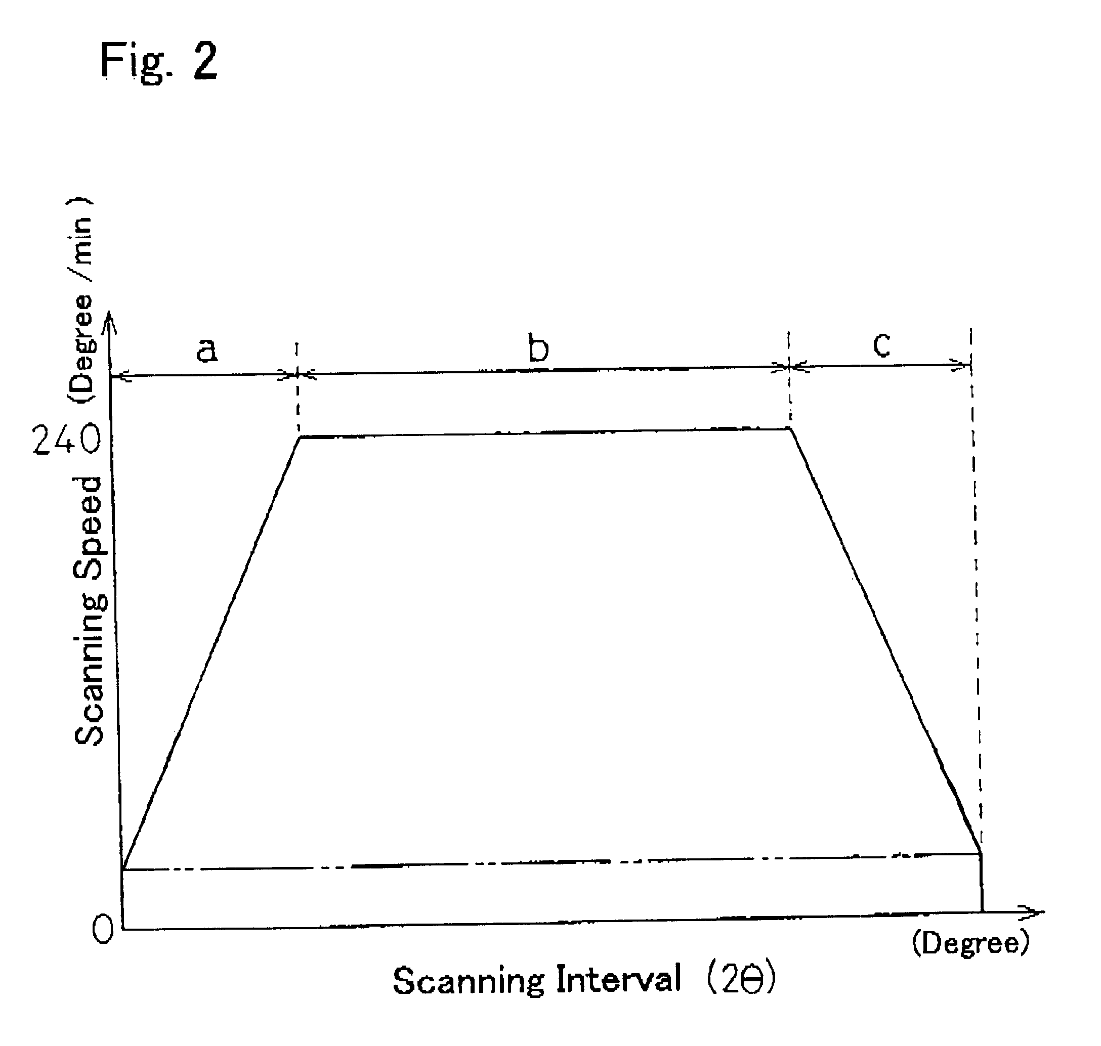
As described above, with the apparatus according to the present invention, the counting time counter 15 and the frequency divider 16 are used to determine the counting time for a fixed scanning interval of, for example, 1 / 100 degree, and the correction calculating means 11 is used to correct the count for each scanning interval based on the corresponding counting time. Accordingly, when the linkage means 10 is driven at a high speed, an accurate intensity of the fluorescent X-ray for each scanning interval including in the driving ranges of accelerated and decelerated speed (shown by `a` and `c` in FIG. 2) can be obtained. Accordingly, the qualitative analysis or the semi-quantitative analysis can be rapidly and accurately performed over the relatively wide range of wavelength in the fluorescent X-ray analysis. In other words, a rapid and accurate analysis is possible with the continuous scanning feature.

Besides, the linkage means 10 is driven by the pulse motor in the apparatus des...

second embodiment

With the apparatus of the second embodiment described above, the counting time counter 15 and the frequency divider 16 are used to determine the counting time for a fixed scanning interval and the correction calculating means 11 is used to correct the count for each scanning interval based on the corresponding counting time. Accordingly, an accurate intensity of the diffracted X-ray for each scanning interval can be obtained and also a rapid and accurate analysis is possible with the continuous scanning technique in the X-ray diffraction analysis. Moreover, since the frequency divider 16 generates the read-out signal based on, not the pulses to be supplied to the pulse motor for driving the linkage means 20, but the signals .alpha. and .beta. from the high resolution rotary encoder 30 mounted on the main rotary shaft of the linkage means 20, the count for each scanning interval can also be corrected for an instable condition in which the counting time for each scanning interval flut...

third embodiment

The apparatus in the third embodiment furthermore includes a coating weight calculating means 60 for calculating the amount of silicone coated of the silicone layer 21a for each of the fixed drive range, based on the count that has been corrected by the correction calculating means 11.

The operation of the apparatus will now be described. With respect to the release coated paper 21 being transported upwardly from a lower position at a fixed speed within the range of for example, 100 to 600 m / min, the measuring unit 18 is first moved from left to right by the drive means 40 at a speed of, for example, 20 mm / sec and when the left edge A of the release coated paper 21 enters in the range between the reflection type photo-sensors 50A and 50B as shown in FIG. 7, that is, when the measuring unit 18 (particularly the center of light receiving part in the head 19) is moved to the position at the left edge A of the release coated paper 21, the frequency divider 26, based on a signal fed from ...


PUM

PropertyMeasurementUnit
aaaaaaaaaa
speedaaaaaaaaaa
speedaaaaaaaaaa

Abstract

An X-ray analyzing apparatus capable of accomplish a rapid and accurate analysis is provided in which a detector for X-rays is rotated or shuttled to perform a continuous scanning. Determining a counting time for each of fixed scanning intervals by means of a counting time counter 15 and a frequency divider 16, correction of a count for each scanning interval is made by a correction calculating means 11 on the basis of the corresponding counting time.

Description

1. (Field of the Invention)The present invention generally relates to an X-ray analysis apparatus whose detector part turns or shuttles to accomplish a continuous scanning.2. (Description of the Prior Art)In an X-ray fluorescence spectrometer of a wavelength dispersive type currently widely in use, a sample to be analyzed is irradiated by primary X-rays so that fluorescent X-rays are emitted from the sample. The fluorescent X-rays emitted from the sample are monochromated by a spectroscopic device such as an analyzing crystal, and the resultant, spectroscopically analyzed fluorescent X-rays are then detected by a detector which subsequently outputs pulses. Although the voltage of the pulses outputted from the detector, that is, the pulse height value is proportional to the fluorescent X-ray energy and the number of the output pulses per unitary time is proportional to the intensity of the fluorescent X-rays, of those output pulses the output pulses falling within a fixed range of pu...

Claims


Application Information

Patent Timeline
Patent Type & Authority Patents(United States)
IPC IPC(8): G01N23/223G01N23/22
CPCG01N23/223G01N2223/076
Inventor UEKI, BUNJIROKATO, TOSHIYUKIFUJIMOTO, HIDEAKI
Owner RIGAKU CORP
Why Eureka
Try Eureka