
Timing driven synthesis of sum-of-product functional blocks

Active Publication Date: 2010-06-15
CADENCE DESIGN SYST INC
View PDF36 Cites 10 Cited by
  • Summary
  • Abstract
  • Description
  • Claims
  • Application Information

AI Technical Summary

Benefits of technology

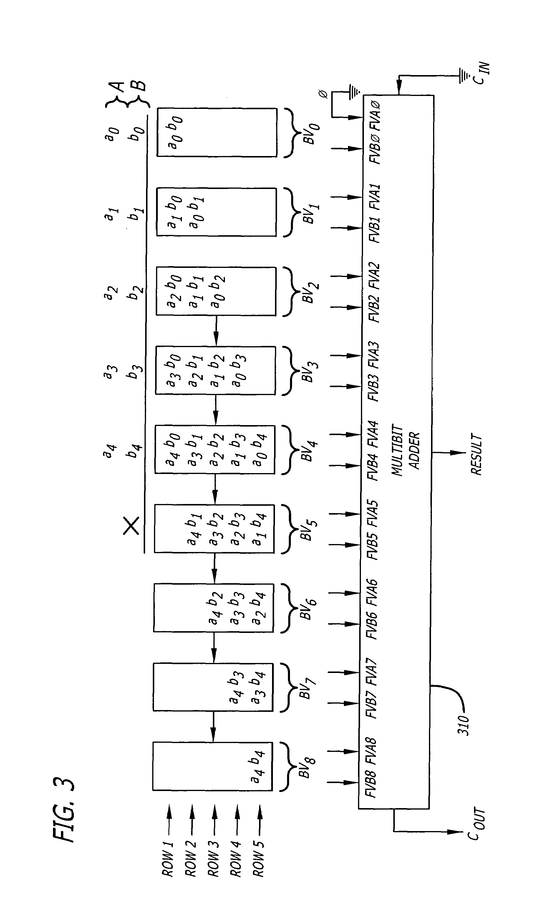
[0008]FIG. 4A is a logic diagram illustrating one exemplary logic synthesis of the reduction of a fourth bit-vector BV3 associated with the multiplication illustrated in FIG. 3.
[0009]FIG. 4B is a logic diagram illustrating another exemplary logic synthesis of the red

Problems solved by technology

In many cases, this is an incorrect assumption because the input signals into functional blocks often arrive at different times.
However, the time spent waiting for the input signals to be valid at the input to the functional block is often not considered and leads to an unexpected increase in the delay of signals through the functional block.

Method used


Image

  • Timing driven synthesis of sum-of-product functional blocks
  • Timing driven synthesis of sum-of-product functional blocks
  • Timing driven synthesis of sum-of-product functional blocks

Examples


Embodiment Construction

[0020]In the following detailed description of the embodiments of the invention, numerous specific details are set forth in order to provide a thorough understanding of the embodiments of the invention. However, it will be obvious to one skilled in the art that the embodiments of the invention may be practiced without these specific details. In other instances well known methods, procedures, components, and circuits have not been described in detail so as not to unnecessarily obscure aspects of the embodiments of the invention.

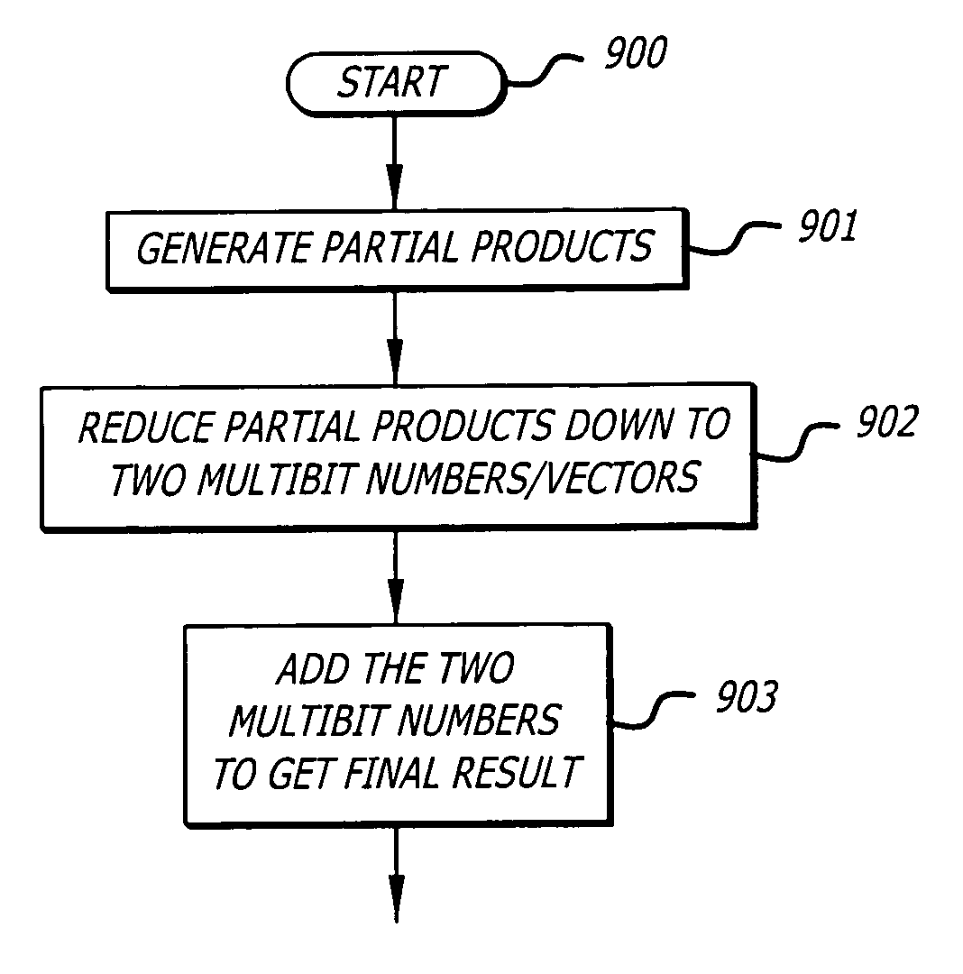
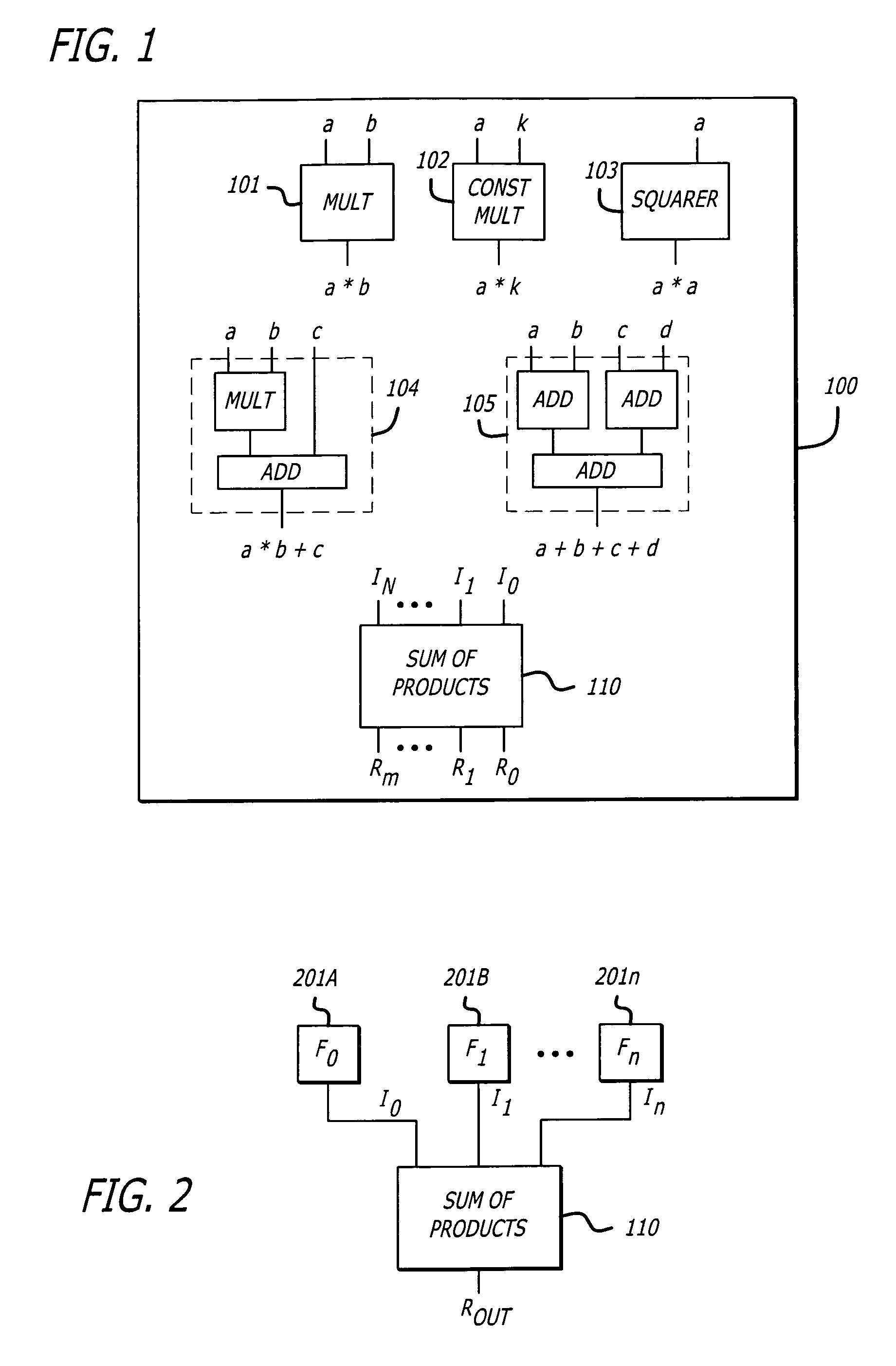
[0021]The embodiments of the invention include a method, apparatus and system for the synthesis of the circuit logic of functional blocks that generally include a sum of products computation. Logic gates are generally selected for the functional blocks in response to the expected timing of input signals generated by other functional blocks.

[0022]A sum of products is a standard form way to express arithmetic functions. The sum of products, in contrast to a prod...


PUM


Abstract

In one embodiment of the invention, an integrated circuit (IC) design tool is provided that has a sum-of-products (SOP) synthesizer. The SOP synthesizer receives expected arrival times of signals including partial product terms of each bit-vector of a SOP functional block, a comparison gate delay, and a register-transfer-level (RTL) netlist in order to synthesize a gate-level netlist of the SOP functional block. The SOP synthesizer includes software modules to synthesize a partial products generator, a partial product reduction tree, and an adder. The synthesis of the partial product reduction tree is responsive to a comparison gate delay and the expected arrival times of the partial product terms in each bit vector.

Description

FIELD[0001]The embodiments of the invention relate generally to electronic design automation (EDA) for integrated circuits. More particularly, the embodiments of the invention relate to timing driven synthesis of sum-of-product functional blocks within integrated circuits.BACKGROUND[0002]Functional blocks in semiconductor integrated circuits are often designed with the assumption that all inputs to the block arrive simultaneously together. That is, the design of the functional block assumes that the all input signals to the block are valid, steady state signals at the same time with respect to a clock signal. In many cases, this is an incorrect assumption because the input signals into functional blocks often arrive at different times.[0003]The design of a function block may require three or more input signals be evaluated simultaneous to produce a resultant output. However, the time spent waiting for the input signals to be valid at the input to the functional block is often not co...

Claims


Application Information

Patent Timeline
IPC IPC(8): G06F7/00
CPCG06F7/5443
Inventor DAS, SABYASACHIGIOMI, JEAN-CHARLES
Owner CADENCE DESIGN SYST INC
Learn More