Method for monitoring a hollow post about a pipe

a technology of hollow posts and pipes, applied in the field of methods for monitoring hollow posts about pipes, can solve the problems of requiring substantial effort, materials and/or time, and requiring a series of equally elevated horizontal support surfaces over a distance, so as to reduce time, effort and materials, and quickly and easily adjust the elevation of the base.

Active Publication Date: 2010-06-22
STRAIGHTN LEVEL FENCING SOLUTIONS
View PDF1 Cites 6 Cited by
  • Summary
  • Abstract
  • Description
  • Claims
  • Application Information

AI Technical Summary

Benefits of technology

[0015]The movement of the lower mounting device along the pipe allows an installer to quickly and easily adjust the elevation of the base on which the hollow post is to be mounted, for example to ensure rails later connected between the posts will extend horizontally to give a neat, pleasant appearance regardless of fluctuations in the ground surface. In this example, once a lower mounting device has been fastened to a first pipe at a desired elevation, the lower mounting device of a neighbouring post can be aligned with that of the first using a laser level, string or other straight line and then fastened in place. Supporting the base on the pipe rather than the ground reduces the time, effort and materials needed to provide alignment of the support surfaces of neighbouring posts.
[0016]The lower mounting device may further comprise an earth-engaging mechanism connected to the body for stabilization thereof. Preferably the earth-engaging mechanism comprises at least one earth piercing element extending downward from the body. Preferably the at least one earth-piercing element comprises a plurality of piercing elements spaced about the pipe receiving passage in the body. The earth engaging mechanism may define the at least one ledge forming the base. The piercing elements allow an additional use of the lower mounting device as a stable position marker for installing the pipe. The piercing elements are driven into the ground to hold the lower mounting device in place to mark a desired post position, after which the pipe can be driven into the ground through the pipe-receiving passage. Depending on where along the pipe the lower mounting device is later fastened to define the base height of the post, the piercing elements may also engage the ground in this fastened position to further stabilize the base.
[0020]There may be provided a second post-engaging mechanism for engagement with a larger post at a distance further from the pipe-receiving passage than the first post-engaging mechanism. The first pipe-engaging mechanism may extend upward from the base further than the second pipe engaging mechanism. Two post-engaging mechanisms on a single lower mounting device allows use of the device with posts of two different sizes to eliminate the need to produce separate devices for each size of post.
[0030]In one embodiment, engaged to separate ones of the pipe and hollow post, the two members of the upper mounting device are movable to their unengaged state through relative motion between the pipe and the hollow post supported thereabout. As a result, the upper mounting device can be adjusted to reposition the hollow post about the pipe upward from the lower mounting device without having to remove the post or otherwise gain access to the upper mounting device.
[0034]Preferably relative rotation between the first and second members of the upper mounting device is prevented by the interlocking in each of the engaged states.
[0053]the optional connection of the attachment facilitating installation of the mounting device on the pipe either without the attachment, so as to engage the hollow post lowered over the pipe at any selected position along the hollow post, or with the attachment, so as to support the bottom end of the hollow post lowered over the pipe sitting atop the base.

Problems solved by technology

Installation of a series of posts to create a substantially horizontal rail assembly may prove difficult in situations where the ground surface features irregularities that deviate from the horizontal, as the support surfaces for some base plates may have to be built up from or recessed into the ground to support neighbouring posts at a common elevation.
For the reasons provided in the preceding paragraph, providing a series of equally elevated horizontal support surfaces over a distance may require substantial effort, materials and / or time.

Method used


Image

  • Method for monitoring a hollow post about a pipe
  • Method for monitoring a hollow post about a pipe
  • Method for monitoring a hollow post about a pipe

Examples


first embodiment

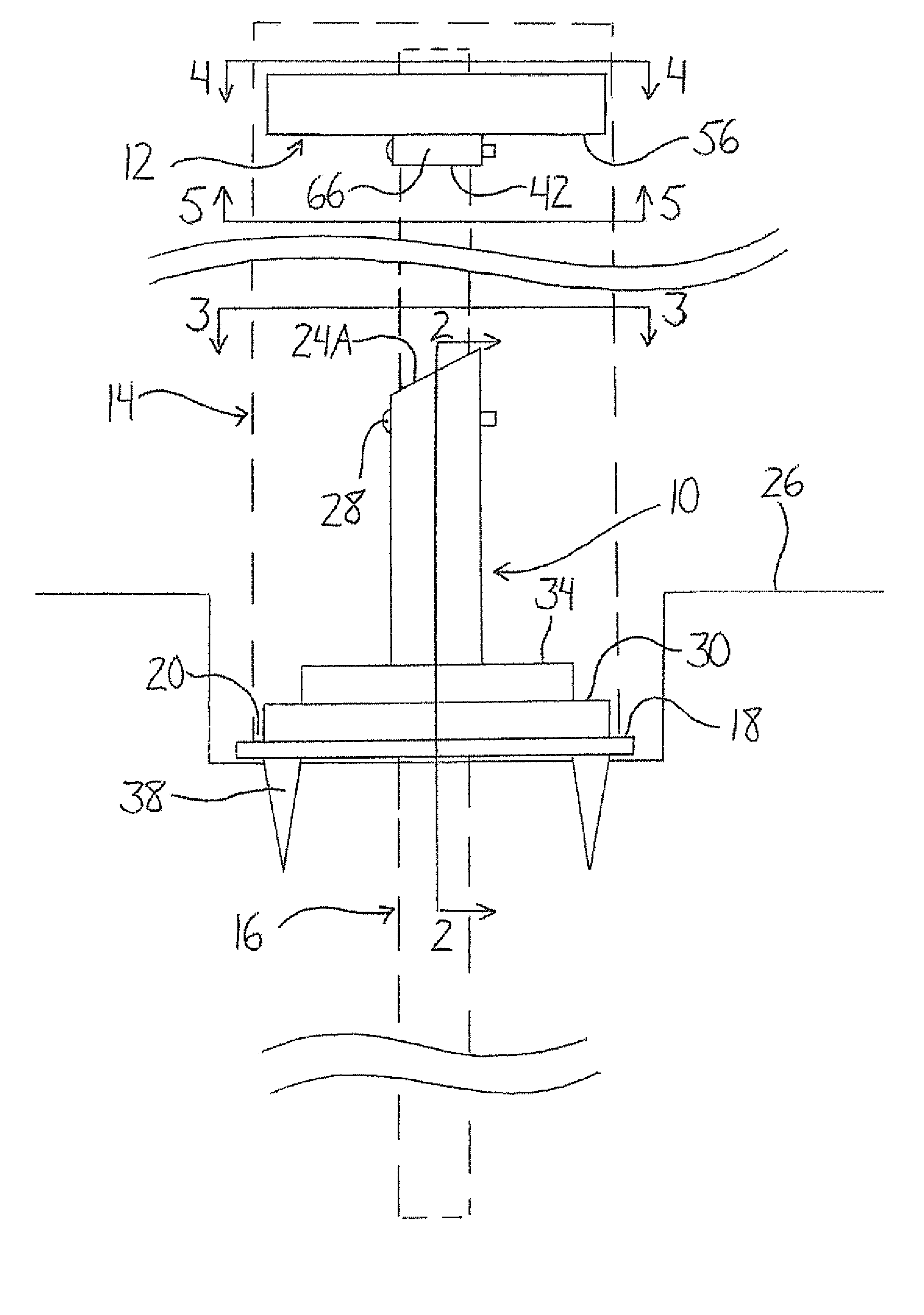
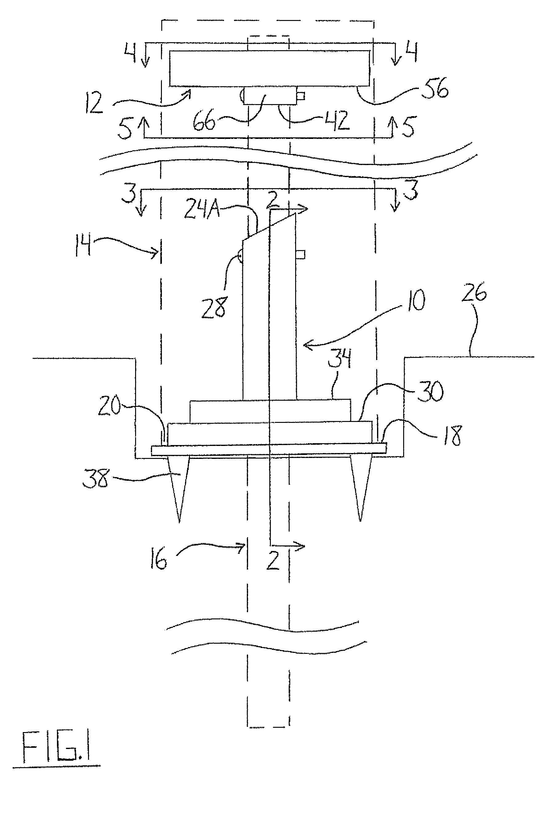
[0095]The upper mounting device 12 is disposed on the pipe 16 a distance upward from the lower mounting device 10 in order to engage the hollow post 14 closer to an upper end 40 thereof and hold it in a certain position about the pipe 16. It is desirable to allow adjustment of such an upper mounting device so as to be able to change this position of the post 14 relative to the pipe 16 at the upper end 40. It should be appreciated that the pipe 16 may not have been installed so as to extend in a completely vertical manner, but that supporting the post 14 about the pipe 16 with a relative degree of tilt between them may allow the post 14 to be supported in a vertical manner without having to first reorient the pipe 16. After installation of the upper mounting device 12 and the hollow post 14 around the pipe 16, if it is found that further adjustment is necessary as the hollow post 14 is not quite vertical, the upper mounting device 12 of the first embodiment allows such adjustment wit...

third embodiment

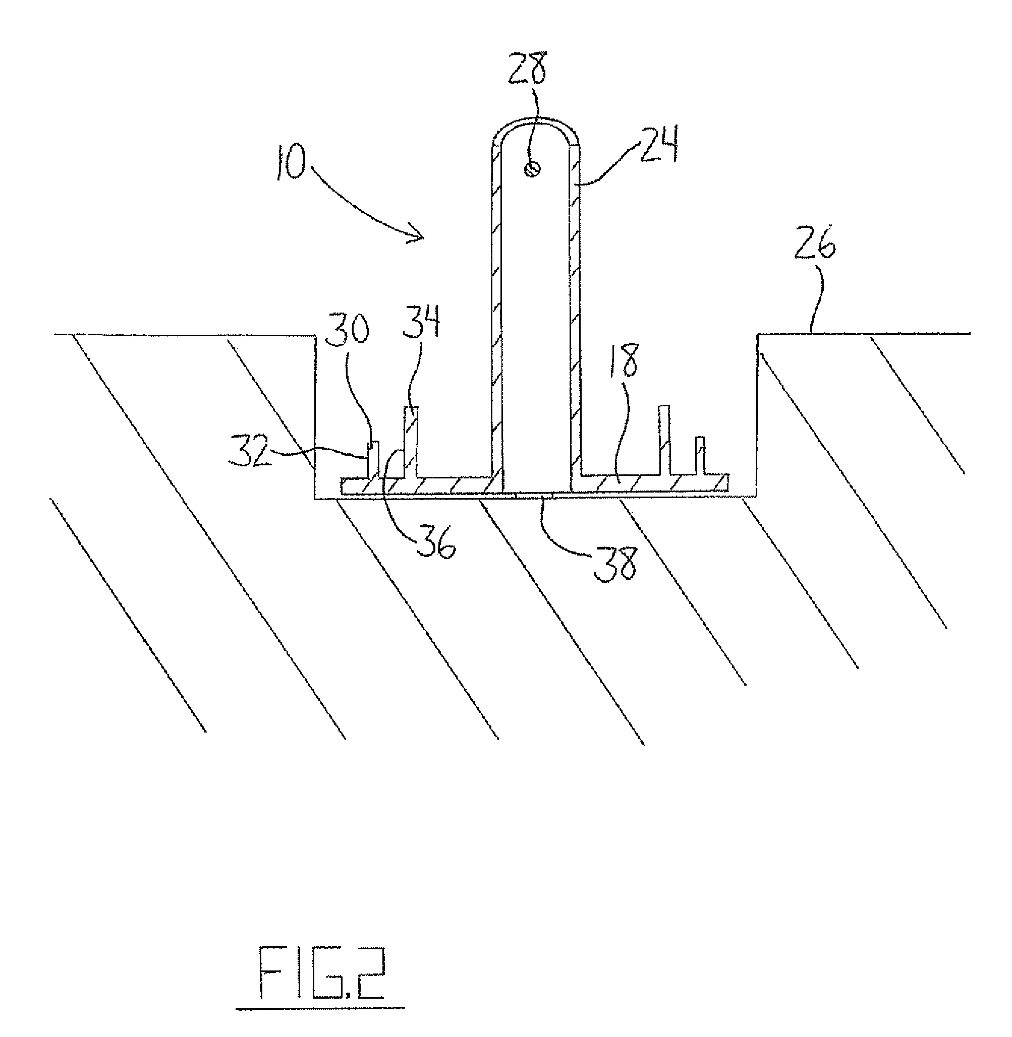
[0115]FIG. 12 shows a third embodiment mounting device 70 that can be used to position a hollow post 14 about a pipe 16. The device includes an inner cylinder 72 disposed concentrically within an outer cylinder 74. The two cylinders are attached to one another by a web 76 spanning the space between them at the upper end of the outer cylinder 74. Fins 78 also connect the two cylinders by extending radially between the inner surface of the outer cylinder 74 and the outer surface of the inner cylinder 72. Along the common axis of the two cylinders, the inner cylinder 72 is longer than the outer cylinder 74 and extends beyond both ends thereof. On its own, the mounting device 70 has similarities to the lower mounting device 10 described above and shown in FIGS. 1 to 3. The web 76 has a pipe-receiving opening therein as defined by the inner cylinder 72 which acts as the pipe collar. The outer cylinder 74 forms an outer annular wall sized to engage the inner surfaces of a hollow post lowe...


PUM

PropertyMeasurementUnit
heightaaaaaaaaaa
heightsaaaaaaaaaa
durabilityaaaaaaaaaa

Abstract

Systems use mounting devices arranged to support a hollow post on or position the hollow post around a pipe. One lower mounting device slides along the pipe prior to fastening thereto to allow change or adjustment of a height at which the hollow post is to be supported on a base of the device. Another mounting device can be used with or without a base-defining attachment to facilitate selective use of the device to either support the bottom end of the post on the optional base or instead just engage the post's interior surface at any point along the post for positioning thereof about the pipe. Another mounting device is directly fastenable to the pipe through a wall projecting from the device's body or alternatively cooperable with a second body mountable on the pipe for engagement with this second body in different positions relative to the pipe.

Description

[0001]This application is a continuation-in-part of U.S. application Ser. No. 11 / 370,173, filed Mar. 8, 2006, and claims foreign priority benefits from Canadian Patent Application No. 2,581,717 filed Mar. 8, 2007.[0002]This invention relates to a system for mounting a hollow post about a pipe and more particularly relates to a system having upper and lower mounting devices supported on the pipe at spaced heights therealong to engage the hollow post.BACKGROUND OF THE INVENTION[0003]Plastic or vinyl rail assemblies, for example for use in fencing and decking, are gaining popularity due to their durability and pleasant appearance. Unlike wood used in conventional fencing or decking rail assemblies, the plastic or vinyl components do not require post-sale painting and weatherproofing and will not rot over time. Rail assemblies feature horizontal rails supported on and extending between vertical posts spaced apart along a straight line. Plastic or vinyl posts are usually manufactured to ...

Claims


Application Information

Patent Timeline
Patent Type & Authority Patents(United States)
IPC IPC(8): B21D47/00E02D27/42
CPCE04H12/2253E04H12/2215E04F2011/1897Y10T29/49616
Inventor FROESE, JOSEPH S.
Owner STRAIGHTN LEVEL FENCING SOLUTIONS
Why Eureka
Try Eureka