Container for physiological fluids

a technology for physiological fluids and containers, applied in the field of containers for physiological fluids, can solve the problems of affecting the health of patients, affecting the treatment effect of patients,

Active Publication Date: 2010-06-22
FUTURE PATH MEDICAL
View PDF52 Cites 48 Cited by
  • Summary
  • Abstract
  • Description
  • Claims
  • Application Information

AI Technical Summary

Benefits of technology

[0011]In another aspect of the present invention, a container for fluid includes a first chamber for containing fluid and a second chamber for containing fluid. A sensor in the second chamber senses a property of fluid in the second chamber. A releasable device prevents fluid from flowing from the first chamber to the second chamber. The releasable device permits fluid to flow from the first chamber into the second chamber upon release of the releasable device.

Problems solved by technology

Further, patients can sometimes obstruct the flow of urine into the container by lying on and possibly crimping the drain tube.
Both a filled container and blocked input tube can cause urine backup into the bladder and a backup condition can have a deleterious effect on the patient's health.
Also, the urine can spill onto the patient's bed linen and potentially cause / worsen various skin problems associated with being bedridden.
This manual process is time consuming (i.e., costly) and could also lead to problems associated with handling of urine, which is a biohazard.

Method used


Image

  • Container for physiological fluids
  • Container for physiological fluids
  • Container for physiological fluids

Examples


Embodiment Construction

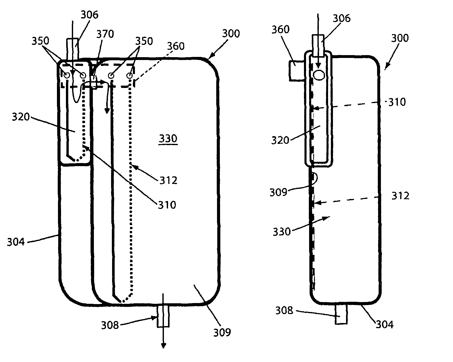
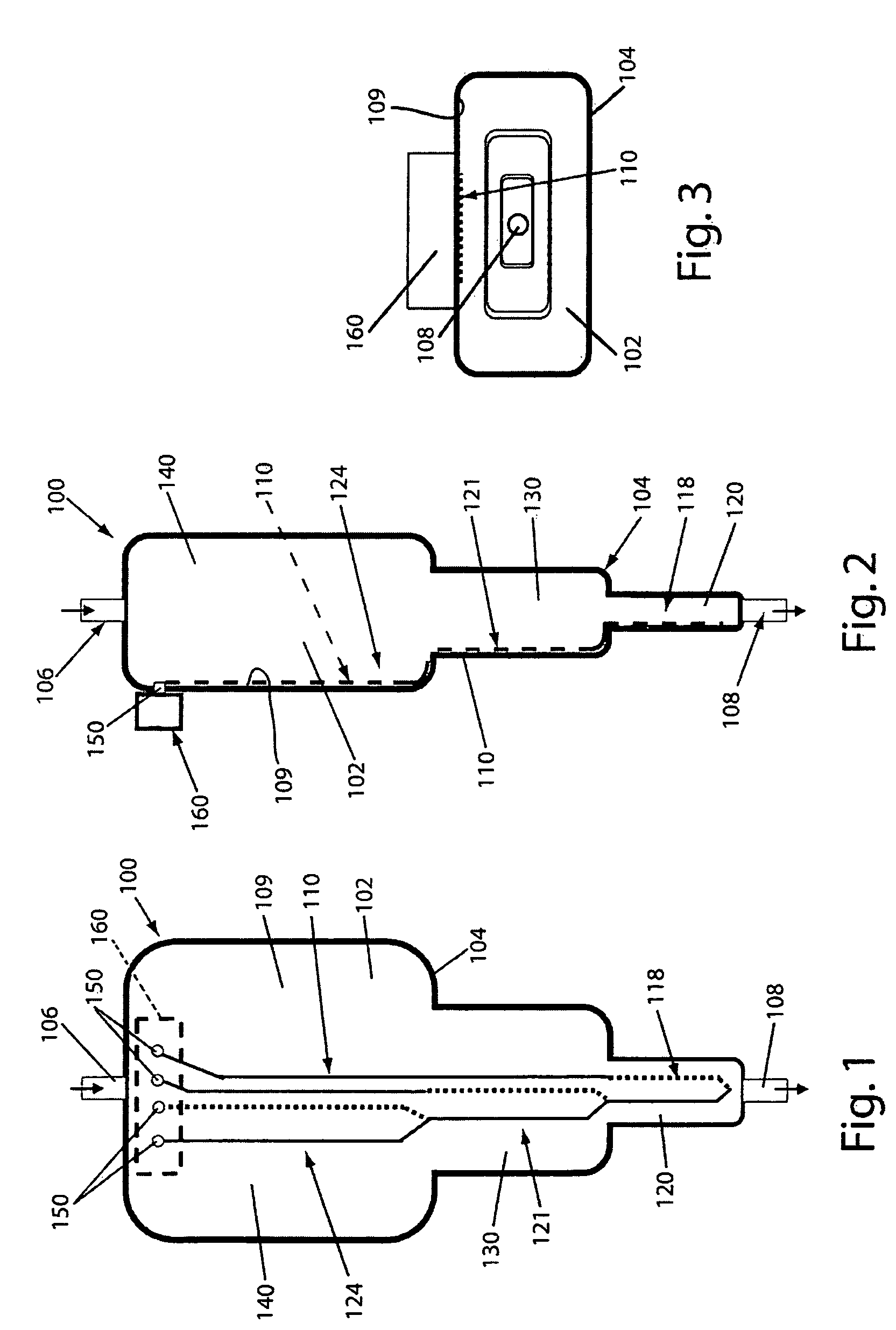
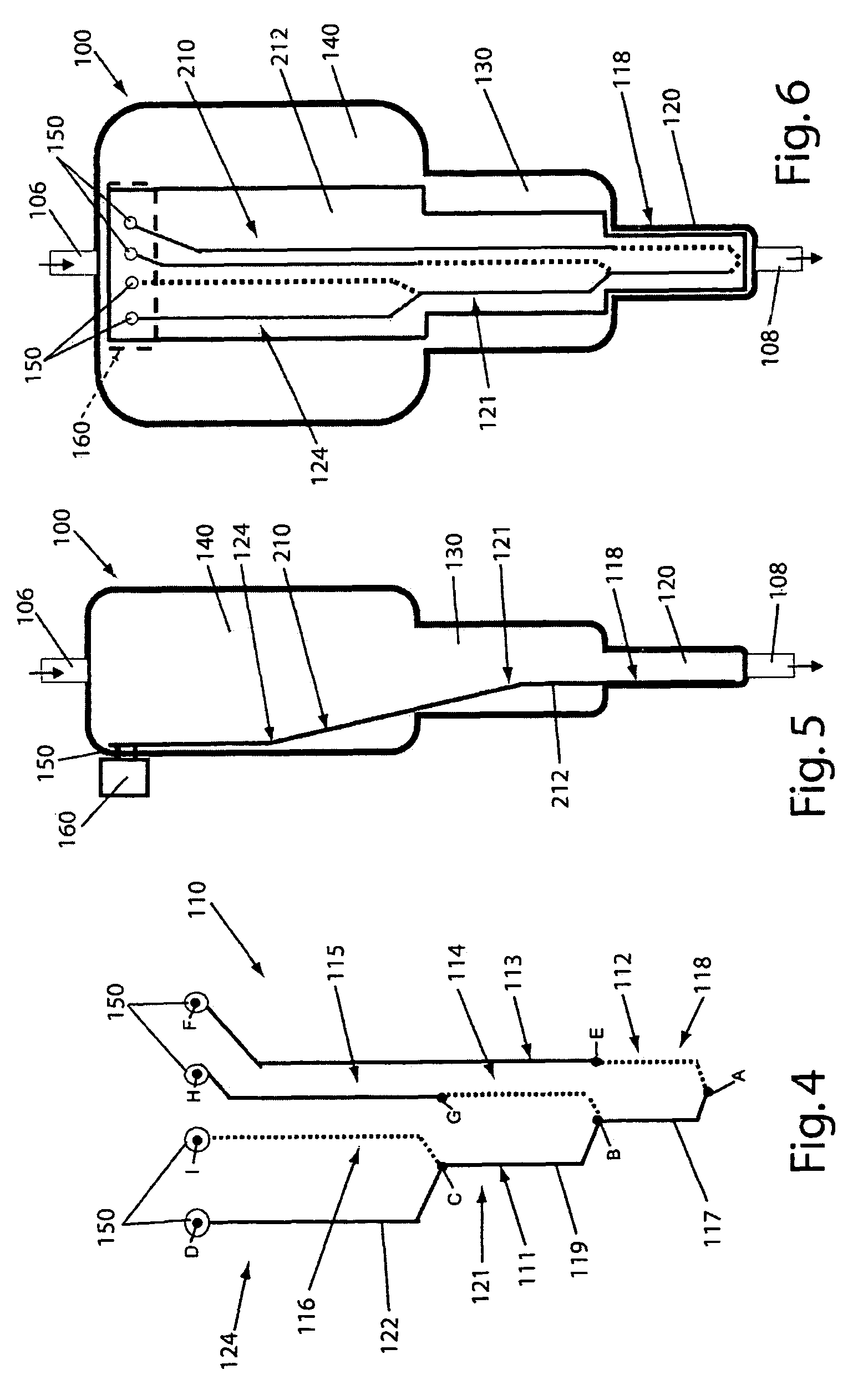
[0048]A container 100 constructed in accordance with a first exemplary embodiment of the present invention is shown in FIGS. 1-4. The container 100 may be a rigid or flexible container having a wall 104 that forms an overall interior chamber 102 that has a total volume VT. Fluid, such as physiological fluid, flows into the chamber 102 through an inlet 106. The physiological fluid may be urine from an indwelling urinary catheter or wound drainage fluid from a trans-abdominal drainage catheter. An outlet valve 108 may be used to allow fluids to flow from the container 100 for disposal or for delivery to a patient.

[0049]The container 100 includes a plurality of interconnected regions or chambers 120, 130, and 140. Although three chambers 120, 130 and 140 are shown, it is contemplated that the container 100 may have any desired number of chambers. Each chamber 120, 130, and 140 has a different volume (i.e., V1, V2, V3) and the volume of the chambers adds up to a total volume of VT=V1+V2...


PUM


Abstract

A container includes a chamber for containing fluid. At least one sensor is disposed within the chamber for sensing a property of fluid in the container. A unit that receives a signal from the sensor communicates with a device that displays the property of the fluid in the container. The container may include first and second chambers. A first sensor is disposed within the first chamber. The first sensor is in contact with fluid in the first chamber. The first sensor senses a volume of fluid in the first chamber. A second sensor is disposed within the second chamber. The second sensor is in contact with fluid in the second chamber. The second sensor senses a volume of fluid in the second chamber. A diverter may direct fluid from an inlet to a bottom portion of the chamber and prevents the fluid from contacting the sensor. A releasable device may prevent fluid from flowing from the first chamber to the second chamber. The releasable device permits fluid to flow from the first chamber into the second chamber upon release of the releasable device. An element of the sensor may have a first portion with an electrical resistance per unit length greater than an electrical resistance per unit length of a second portion of the element. A shunt resistor extending between lower portions of first and second elements of the sensor may have a resistance equal to approximately 0.08 times a resistance of the sensor when the chamber is empty.

Description

RELATED APPLICATION[0001]This application claims priority from U.S. Provisional Patent application Ser. No. 60 / 861,632, filed Nov. 29, 2006, the subject matter of which is incorporated herein by reference.FIELD OF THE INVENTION[0002]The present invention relates to a container for physiological fluid, and more specifically, to a container that senses characteristics of the physiological fluid in the container.BACKGROUND OF THE INVENTION[0003]For a variety of reasons, it is desirable to supply fluids, such as electrolytes, to a patient or to collect physiological fluids from a patient in various settings including hospitals, nursing homes, private homes, or wheel chairs. For example, there are many instances of patient treatment where it is necessary to collect and determine, at all times, the accurate amount of expelled body fluids, such as urine, that is being released by the patient. It is, in fact, conventional in hospitals to collect urine from certain patients to measure and mo...

Claims


Application Information

Patent Timeline
Patent Type & Authority Patents(United States)
IPC IPC(8): G01F17/00
CPCA61B10/007G01F23/24A61F5/4404A61B10/0096
Inventor BOIARSKI, ANTHONY A.
Owner FUTURE PATH MEDICAL
Why Eureka
Try Eureka