Single shell-pass or multiple shell-pass shell-and-tube heat exchanger with helical baffles

a heat exchanger and helical baffle technology, which is applied in the direction of indirect heat exchangers, stationary tubular conduit assemblies, lighting and heating apparatus, etc., can solve the problems of reduced service life, increased power load, and decreased transfer rate, so as to prolong cleaning interval, reduce power load, and improve heat transfer rate. effect of heat exchanger and heat exchanger efficiency

Inactive Publication Date: 2010-06-22
XI AN JIAOTONG UNIV
View PDF28 Cites 19 Cited by
  • Summary
  • Abstract
  • Description
  • Claims
  • Application Information

AI Technical Summary

Benefits of technology

[0009]To overcome the above defects, one fundamental object of the present invention is to provide a shell-and-tube heat exchanger with helical baffles, its structure being such that the fluid flow in the shell-sides is in a more desirable pattern, the flow pressure drop is decreased and the heat transfer rates are increased. Meanwhile, the structure of the shell-and-tube heat exchanger with helical baffles according to the present invention renders the configuration of baffles at the portion next to the central axis more desirable when the pitch is large, which facilitates fluid flow and heat exchanging and makes manufacture thereof easier.
[0010]In addition, the present invention provides manufacture methods for outer helical baffles of the shell-and-tube heat exchanger with helical baffles. Such methods may overcome the problem that it is difficult to manufacture the curve of continuous helical baffles and to position and form holes.

Problems solved by technology

There exist many problems in the conventional segmental baffles, e.g., (1) a high pressure drop occurs since the segmental baffles make fluid perpendicularly impact the shell wall and the tubes, leading to an increased power load; (2) the fluid with high speed crosses the heat exchange bundles laterally, inducing vibrations of heat exchange tubes and thus a reduced service life; (3) the heat transfer rates decrease due to a flow stagnation region generated at the joint of baffles and shell walls, where fouling tends to accumulate as well; and (4) the mass flow rate laterally crossing tube bundles is efficiently decreased due to the bypass flows and leaking flows which exist between baffles and shell walls and between heat exchange tubes and baffles, resulting in a reduced heat transfer rate on the shell side.
However its manufacture is more complicated than in the case of non-continuous helical baffles.
This is especially the case when the pitch is large, that is, the helical surface becomes relatively steep in portions close to the central axis, which makes it more difficult, or even impossible to manufacture curved surfaces and to position and form holes on these surfaces.
This somehow mitigates the difficulty in the manufacture of continuous helical baffles, however, it relatively decreases the efficient heat exchange area of heat exchangers since no fluid passes through the central tube, and the diameter of the central tube increases with the increase of baffle pitch.
While its pressure loss is lower than that of a traditional heat exchanger with segmental baffles, however, its heat exchange capacity is also lower, simultaneously which can hardly meet users' requirement.
However, there is a relatively large leakage, which affects heat exchange.
This has an advantage that pressure drop and leakage are reduced and heat transfer coefficient is higher, however, when the pitch is large, the helical surface becomes relatively steep at portions close to the central axis, where it is difficult to manufacture the continuous helical surfaces.
However, as heat exchange tubes can not be arranged at the location of the central tube, the effective heat exchange area of the heat exchanger is relatively decreased, and part of the heat exchanger volume is occupied, thus leading to a decreased compactness.
The continuous helical baffles may reduce leakage, however when the fluid on the shell side is such a medium that tends to foul, fouling can accumulate at the bottom of the horizontally arranged shell-and-tube heat exchanger due to a low flow rate.
Especially when the helical angle is small, a large amount of fouling will deposit and cleanup becomes difficult, thus resulting in a decreased heat transfer rates.

Method used


Image

  • Single shell-pass or multiple shell-pass shell-and-tube heat exchanger with helical baffles
  • Single shell-pass or multiple shell-pass shell-and-tube heat exchanger with helical baffles
  • Single shell-pass or multiple shell-pass shell-and-tube heat exchanger with helical baffles

Examples


Embodiment Construction

[0061]Hereinafter, detailed explanations will be given to the present invention with references to the drawings.

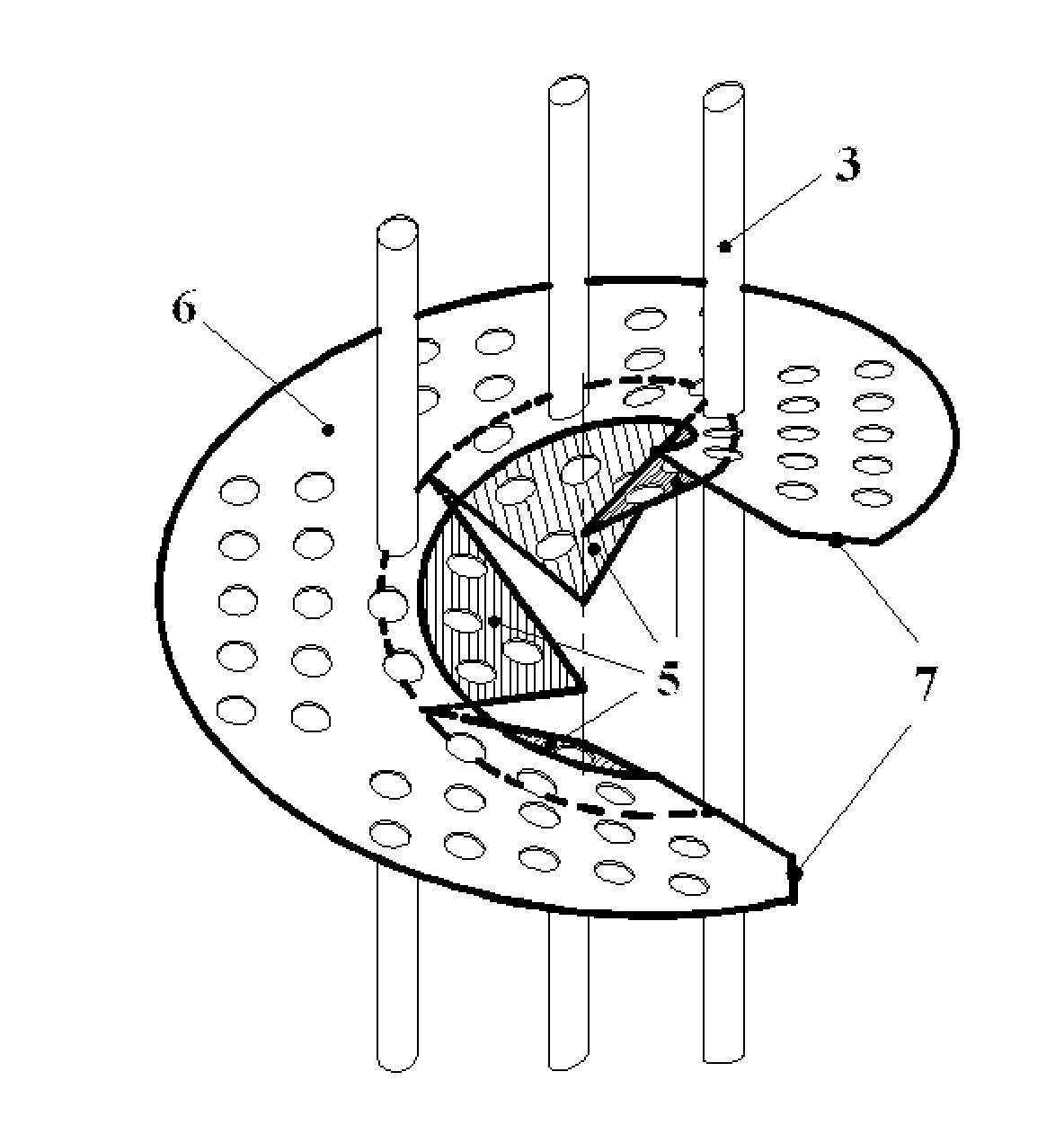
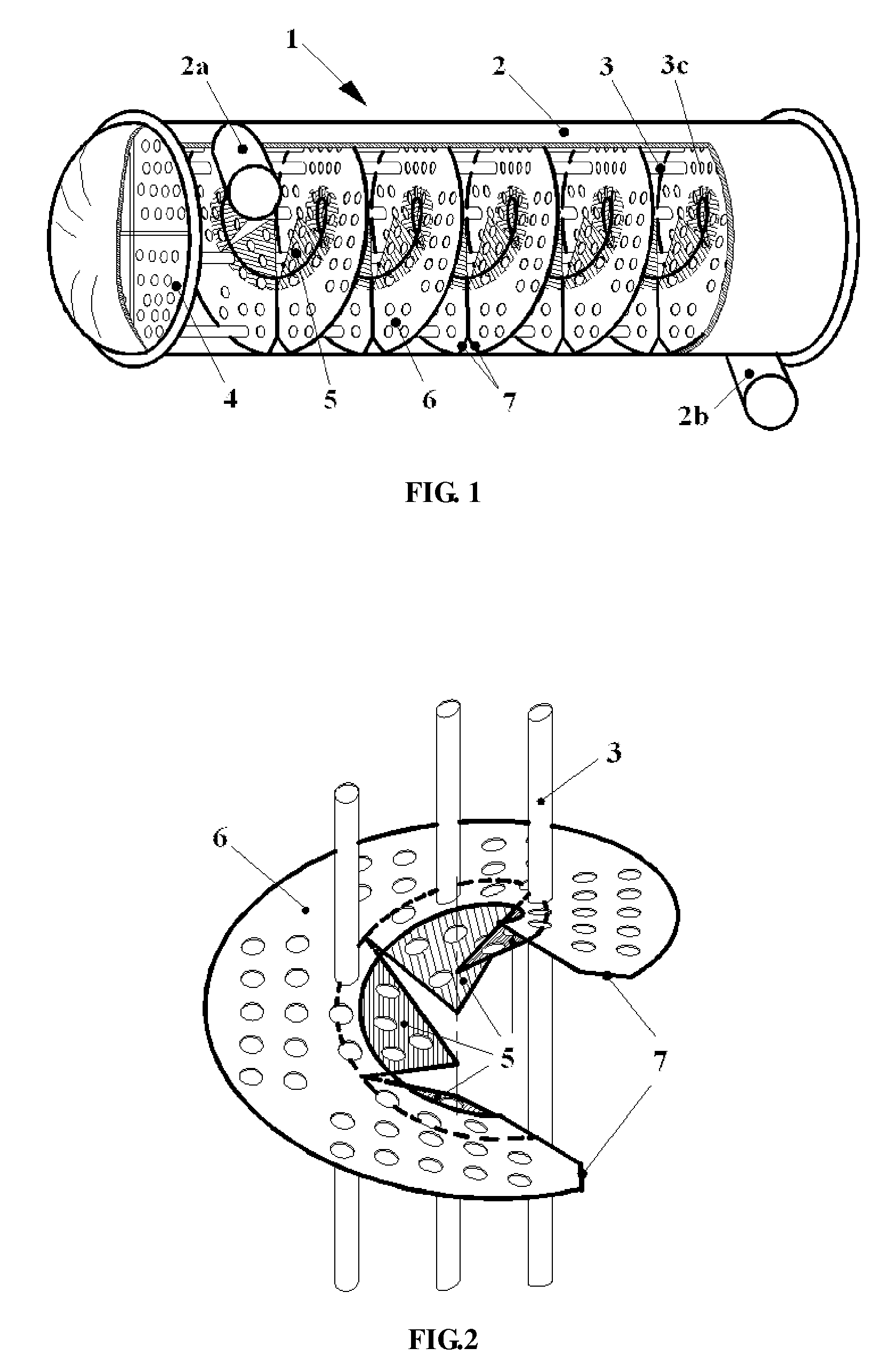
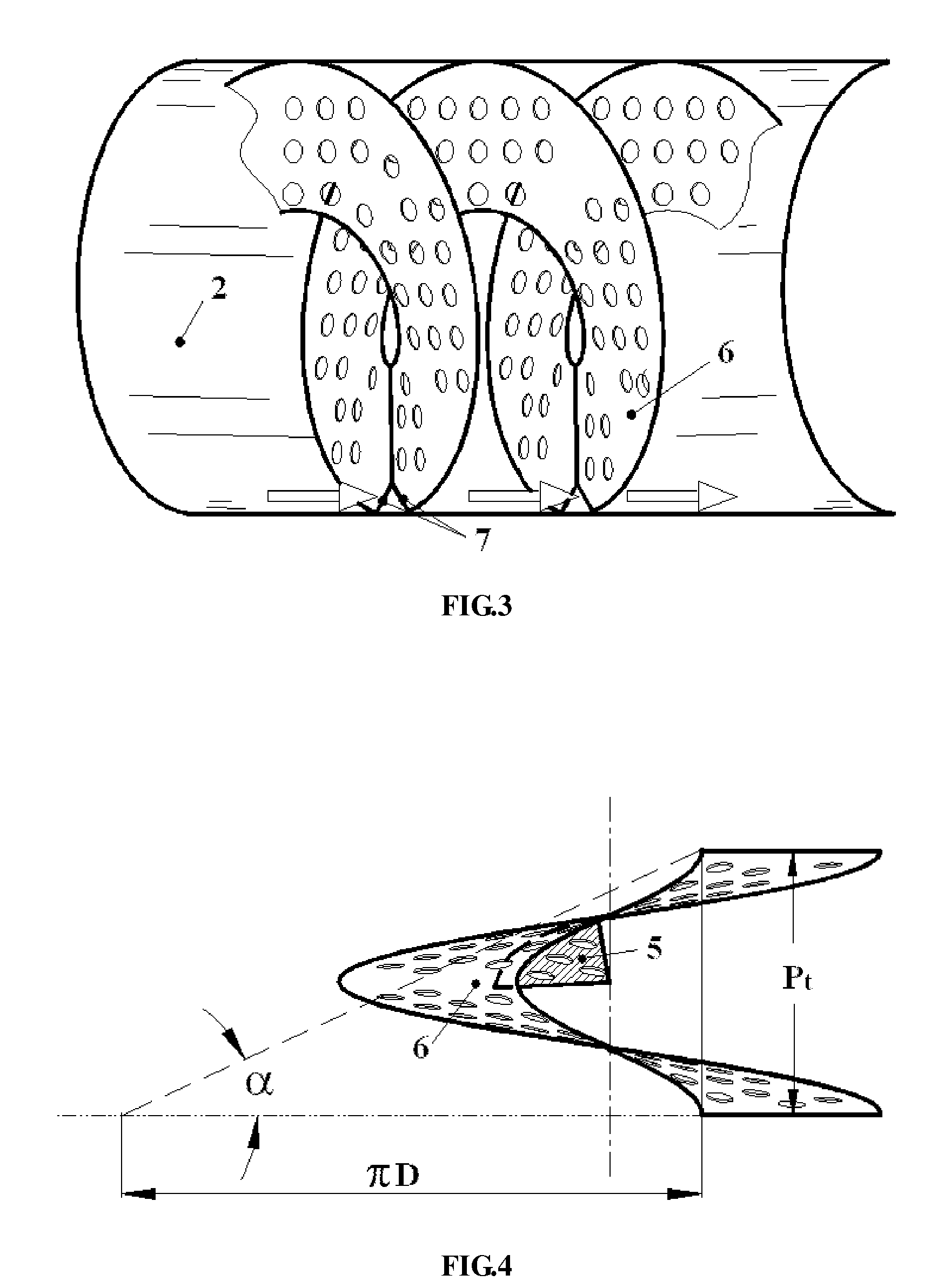
[0062]As shown in FIG. 1, the shell-and-tube heat exchanger with combined helical baffles according to present invention comprises a shell body 2, a shell side inlet tube 2a, a shell side outlet tube 2b, a heat exchange tube bundle 3, tube plates 4, inner helical baffles 5, and outer helical baffles 6. The inlet tube on the shell side 2a and the outlet tube on the shell side 2b of the shell body 2 take the form that fluids are introduced into and discharged out laterally. They are mounted to the shell body 2, in close proximity to its outer periphery. Fluid is introduced into and discharged out along the directions tangent to the shell body, such that the behavior of the fluid on the shell side becomes more similar to helical flows and the local pressure drop at the inlet and the outlet are reduced. The heat exchange tube bundle 3 penetrates through the inner and out helic...


PUM

PropertyMeasurementUnit
heat transfer rateaaaaaaaaaa
pressure dropaaaaaaaaaa
speedaaaaaaaaaa

Abstract

The present invention provides a single shell-pass shell-and-tube heat exchanger with helical baffles, where within a single pitch, the helical baffles are separated into inner and outer parts along the radial direction of the shell. In the central portion of the inner space of the shell, an inner non-continuous helical form is employed; in other portion outside the central portion, doughnut shaped helical baffles with continuous curved surfaces are arranged to form an outer continuous helical baffle, and the outer helical baffles are arranged to surround the inner helical baffles. Furthermore, the present invention relates to a multiple shell-pass shell-and-tube heat exchanger with helical baffles, in which complete continuous helical baffles are provided in shell-sides other than the inner shell-pass, while non-continuous helical baffles or other flow guide means are employed in the inner shell-pass. The present invention makes flow patterns of fluids on the shell side more desirable, leading to a reduced flow pressure drop, and mitigate fouling, thus the heat transfer rate is improved and the service life of the heat exchanger is increased. The present invention also provides two methods for manufacture of continuous helical baffles, which ensure the concentricity of the tube bundle holes on each continuous helical baffle so as to facilitate installation of heat exchange tube bundles.

Description

FIELD OF THE INVENTION[0001]The present invention relates to a shell-and-tube heat exchanger used in petrochemical industry, energy power industry, metallurgical industry, refrigeration engineering and seawater desalination, especially to a single shell-pass shell-and-tube heat exchanger with helical baffles and a multiple shell-pass shell-and-tube heat exchanger with helical baffles, and also relates to a manufacture method for outer helical baffles of a shell-and-tube heat exchanger with helical baffles.BACKGROUND OF THE INVENTION[0002]Among others, heat exchangers are important apparatuses that are widely used in petrochemical industry, energy power industry, metallurgical industry, refrigeration engineering and seawater desalination. Among heat exchange equipments, the shell-and-tube heat exchangers are predominant, accounting for about 55-70%. This type of heat exchanger has a simple structure that mainly contains two parts, i.e., heat exchange tube bundles and shells. When one...

Claims


Application Information

Patent Timeline
Patent Type & Authority Patents(United States)
IPC IPC(8): F28D7/16F28F9/24
CPCF28D7/1607F28F9/0131F28F9/22Y10T29/49377F28F2009/228Y10T29/4935
Inventor WANG, QIUWANGCHEN, QIUYANGZHANG, DONGJIEZENG, MINWU, YININGGAO, QIANG
Owner XI AN JIAOTONG UNIV
Why Eureka
Try Eureka