
Method and system for real time motion picture segmentation and superposition

a real-time motion picture and superposition technology, applied in the field of video image processing, can solve the problems of unsuitable use for many applications and formidable problem of picture segmentation

Inactive Publication Date: 2010-06-22
RATEZE REMOTE MGMT LLC
View PDF143 Cites 14 Cited by
  • Summary
  • Abstract
  • Description
  • Claims
  • Application Information

AI Technical Summary

Benefits of technology

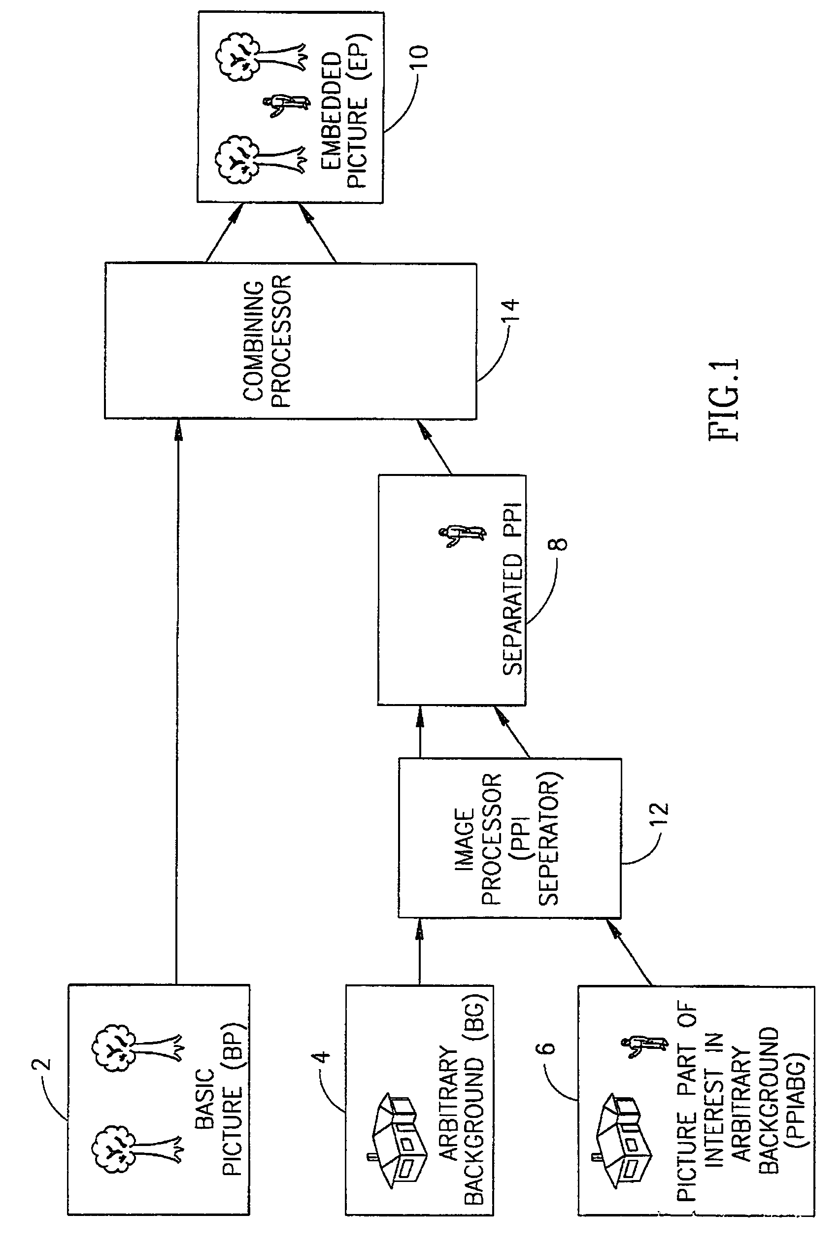
[0012]The present invention relates to processing video images and, in particular, to picture segmentation and superposition of real time motion pictures. The images processed can be in arbitrary, non-standardized backgrounds. The images can be video images with the picture part of interest moving in and out of focus.

Problems solved by technology

As is well known, picture segmentation is a formidable problem.
Therefore, their use is unsuitable for many applications where these standardized conditions can not be or are usually difficult to meet.

Method used


Image

  • Method and system for real time motion picture segmentation and superposition
  • Method and system for real time motion picture segmentation and superposition
  • Method and system for real time motion picture segmentation and superposition

Examples


first embodiment

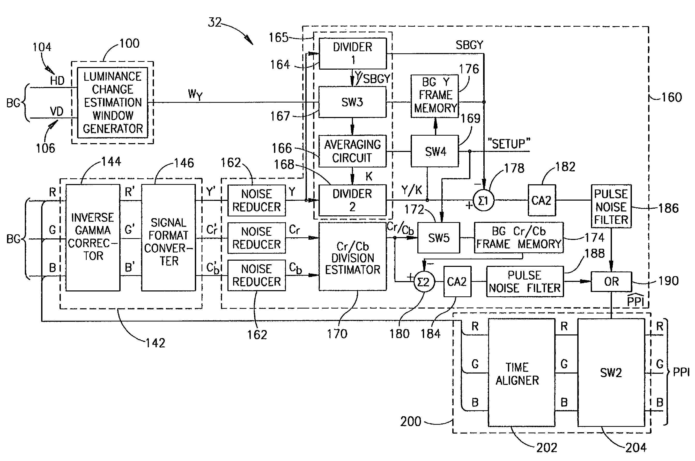
[0074]Reference is now made to FIG. 3 where a block diagram illustration of PPI separator 32 is shown. In this first embodiment, the background BG is a still picture.

[0075]PPI separator 32 is comprised of several units, which include a window building unit 100, a PPI separator unit 200, a mask generator unit 160, and a color signal format converter unit 142. The inputs to PPI separator 32 are the red, blue and green (RBG) signals and genlocked synchronized luminance signals of a frame of the picture part of interest in an arbitrary background (PPIABG) 6.

[0076]Window building unit 100 generates a window used in compensating for variable lighting conditions when moving from frame to frame. Window building unit 100 prepares a window Wy of the background luminance of the current picture part of interest in an arbitrary background (PPIABG) 6.

[0077]Color signal format converter unit 142 changes red, blue and green background (BG) signals of the current PPIABG 6 to luminance, and red and b...

second embodiment

[0094]FIG. 4A illustrates a second embodiment for PPI separation according to the present invention. It comprises a color signal converter 146, a plurality of high pass filters 902, a plurality of pulse signal maximum estimators 904, a plurality of level comparators 905, a plurality of maximum-to-maximum time determiners 906, a plurality of comparators 908, a logical OR gate 910, and a switch 912.

[0095]In FIG. 4A, RBG input signals have their formats converted to Y, Cr and Cb by color signal format converter 146. Each of the signal components Y, Cr and Cb is provided to its own high pass filter 902.

[0096]FIG. 4B illustrates camera modulation transfer functions for focal (graph 951) and non-focal planes (graph 952) as well as the response of high pass filters. The figure presents modulation transfer functions 951 and 952 as a function of the number of pixels per mm for focused (image at the focal plane) and blurred (image not at the focal plane) images, respectively. The figure also ...


PUM


Abstract

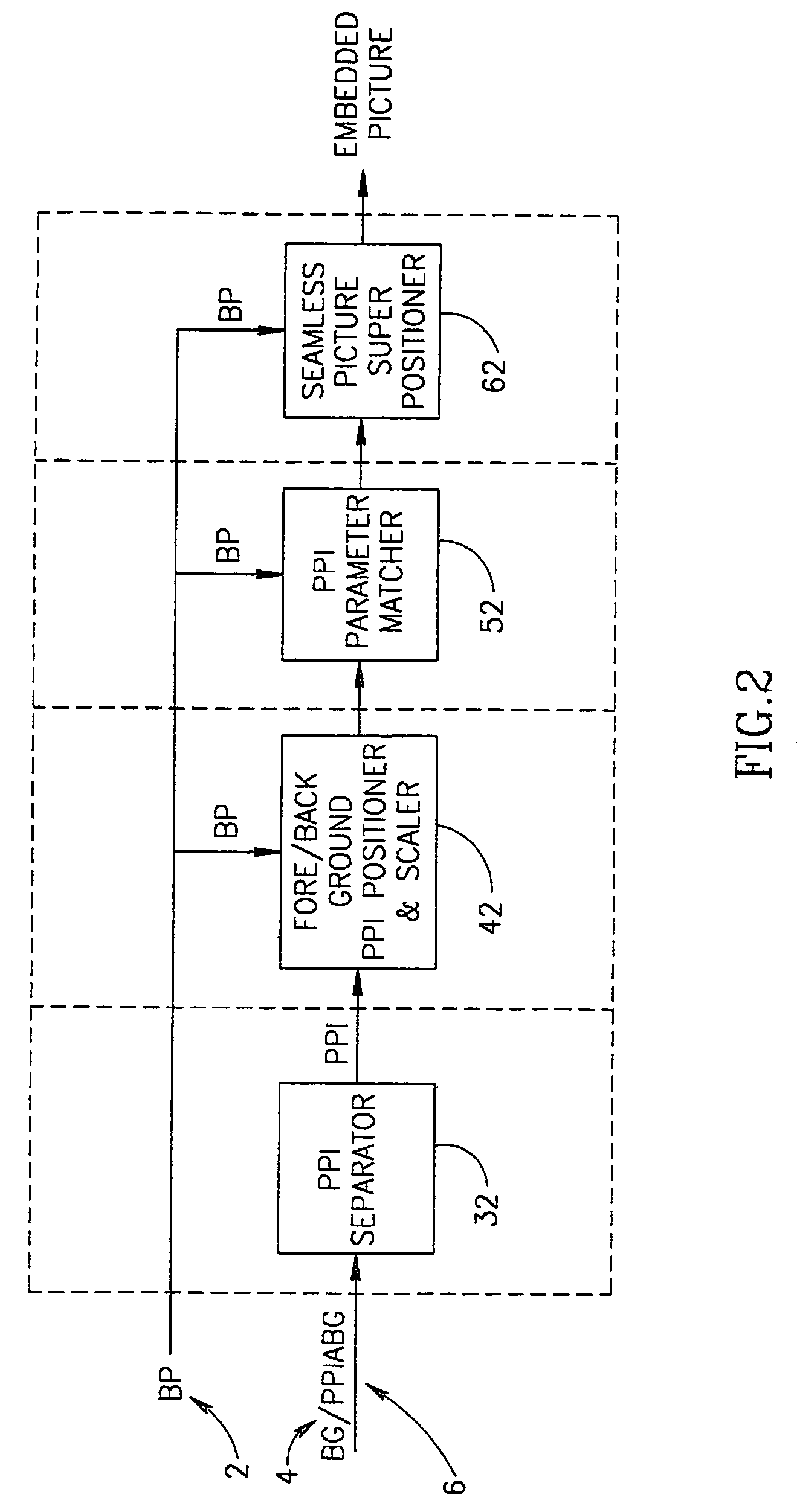
Methods and systems for separating a picture part of interest from an arbitrary background in real time videos are presented. The background may be a moving or still frame. The picture part of interest and background frames may be in or out of focus. One separation approach employs the difference between luminance and chrominance values of the input and background frames where changes in luminance from frame to frame are compensated for. In another approach, picture part of interest separation is based solely on spatial resolution differences between the background and the picture part of interest frames. The present invention also teaches a method and system for parameter matching of the picture part of interest and the basic picture into which the picture part of interest is embedded. The invention further teaches a method and system for embedding a separated picture part of interest into a basic picture containing text.

Description

CROSS-REFERENCE TO RELATED APPLICATIONS[0001]This application is a continuation of and claims priority to U.S. patent application No. 09 / 699,374, filed Oct. 31, 2000, now U.S. Pat. No. 6,753,929 which in turn claims the benefit of and priority to U.S. Provisional Application No. 60 / 214,439 filed Jun. 28, 2000, the disclosures both of which are hereby incorporated by reference herein in their entirety.FIELD OF THE INVENTION[0002]The present invention relates generally to processing video images and, in particular, to picture segmentation and superposition of real time motion pictures.BACKGROUND OF THE INVENTION[0003]The problem of combining parts from different images to create a new superpositioned picture can be decomposed into the following steps: picture segmentation, positioning and scaling, light and spatial parameter matching and superposition of video image parts. As is well known, picture segmentation is a formidable problem.[0004]Picture segmentation involves separating the...

Claims


Application Information

Patent Timeline
IPC IPC(8): H04N9/74H04N5/272
CPCH04N5/272
Inventor SHERAIZIN, SEMION M.SHERAIZIN, VITALY S.
Owner RATEZE REMOTE MGMT LLC
Learn More