Solid electrolytic capacitor

a solid electrolytic capacitor and capacitor technology, applied in the manufacture of electrolytic capacitors, capacitor details, etc., can solve the problems of large lc, lack of uniformity of the obtained solid electrolytic layer, and uneven polymerization state, so as to prevent the decrease of capacity, the effect of increasing the frequency

Active Publication Date: 2010-06-22
SANYO ELECTRIC CO LTD
View PDF4 Cites 8 Cited by
  • Summary
  • Abstract
  • Description
  • Claims
  • Application Information

AI Technical Summary

Benefits of technology

[0016]According to the present invention, stable electrolytic polymerization is possible in the formation of the solid electrolytic layer because an optimum condition for polymerization reaction can be set for each dopant.

Problems solved by technology

However, in the method described in Japanese Patent Laying-Open No. 2005-116777, there is a problem that unevenness in a polymerization state is generated and uniformity of the obtained solid electrolytic layer is lacking because a plurality of types of dopants having different characteristics are contained in the electrolytic polymerization liquid at the same time and optimum conditions of these dopants in a polymerization reaction for forming a solid electrolytic layer are different from each other.
However, there is a problem of large LC.

Method used


Image

  • Solid electrolytic capacitor
  • Solid electrolytic capacitor
  • Solid electrolytic capacitor

Examples


example 1

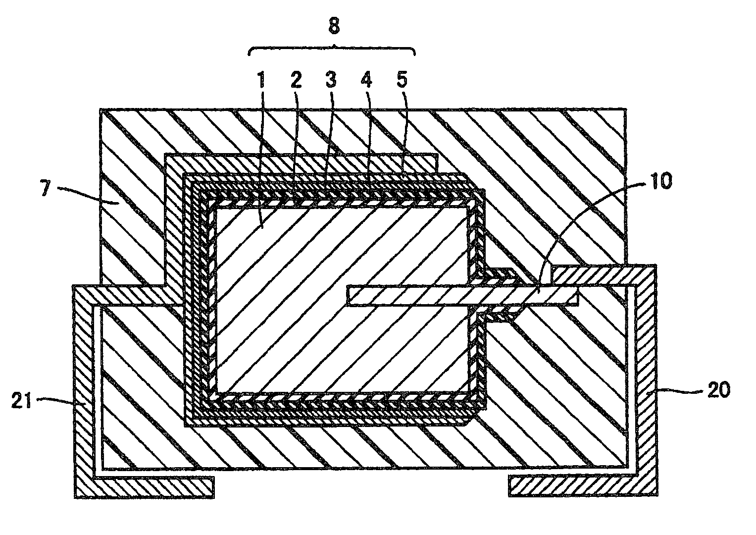
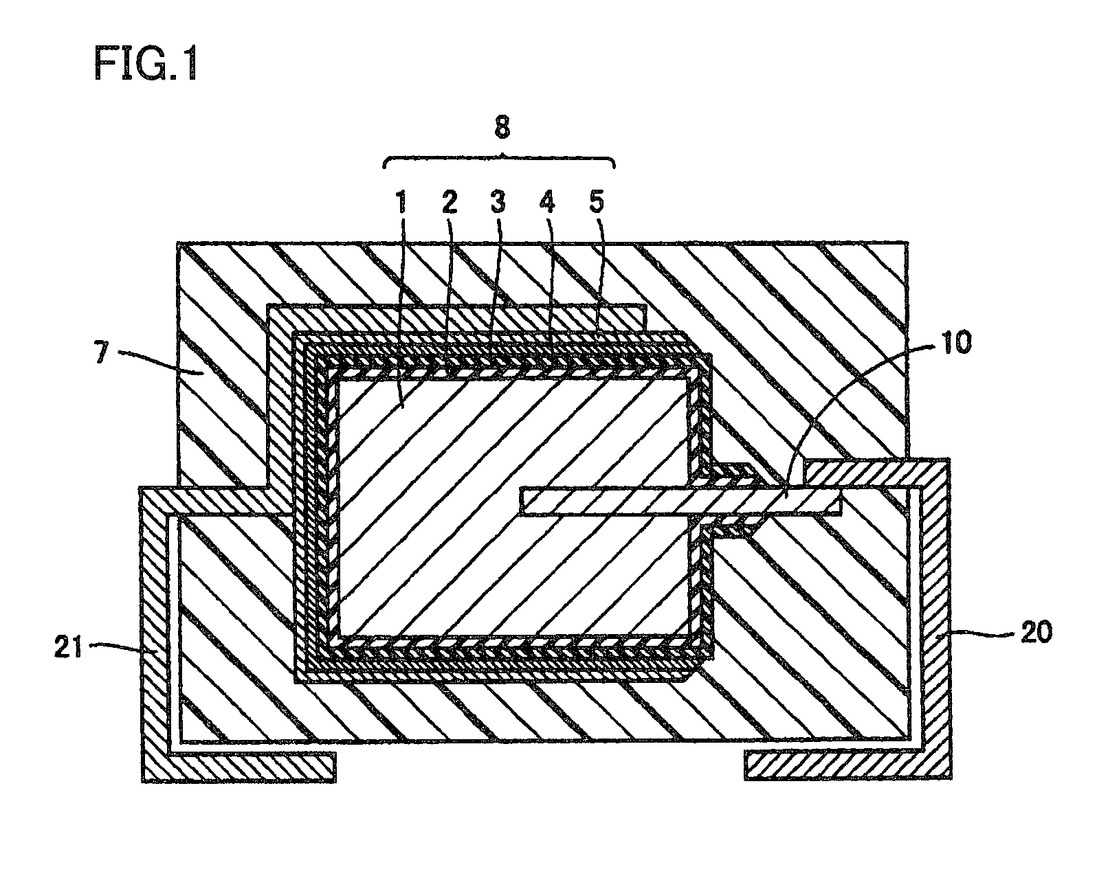
[0062]The solid electrolytic capacitor shown in FIG. 1 was produced with the following method. First, dielectric coating film 2 was formed on the peripheral surface of anode body 1 made of a valve action metal and equipped with anode lead 10. Next, solid electrolytic layer 3 having three layers was formed by forming a conductive polymer layer on the surface of dielectric coating film 2 with a chemical polymerization method in which pyrrole was used as a monomer, forming a first electrolytically polymerized layer using an electrolytic polymerization liquid containing 0.2 mol / l of pyrrole and 0.1 mol / l of an alkylnaphthalene sulfonate ion on the chemically polymerized layer and then forming a second electrolytically polymerized layer using an electrolytic polymerization liquid containing 0.2 mol / l of pyrrole and 0.1 mol / l of a fluoroalkylnaphthalene polysulfonate ion.

[0063]Next, carbon layer 4 and silver paste layer 5 were formed on the surface of the solid electrolytic layer 3 in thi...

example 2

[0064]A solid electrolytic capacitor was produced with the same used amount and method as in Example 1 except for using a naphthalene disulfonate ion instead of a fluoroalkylnaphthalene polysulfonate ion as a dopant used in the formation of the second electrolytically polymerized layer.

example 3

[0065]A solid electrolytic capacitor was produced with the same used amount and method as in Example 1 except for using an alkylbenzene sulfonate ion instead of a alkylnaphthalene sulfonate ion as a dopant used in the formation of the first electrolytically polymerized layer.


PUM

PropertyMeasurementUnit
frequencyaaaaaaaaaa
leakage currentaaaaaaaaaa
equivalent series resistanceaaaaaaaaaa

Abstract

The present invention is a solid electrolytic capacitor having a dielectric coating film, a solid electrolytic layer, and a cathode lead-out layer on a peripheral surface of an anode body in this order, in which the solid electrolytic layer is equipped with at least a first electrolytically polymerized layer and a second electrolytically polymerized layer formed by electrolytic polymerization of the same monomer, and the first electrolytically polymerized layer and the second electrolytically polymerized layer contain a different dopant. With this configuration, a solid electrolytic capacitor is provided that is superior in an ESR characteristic and also superior in heat resistance without deteriorating leakage current.

Description

BACKGROUND OF THE INVENTION[0001]1. Field of the Invention[0002]The present invention relates to a solid electrolytic capacitor using a conductive polymer as a solid electrolyte.[0003]2. Description of the Background Art[0004]In recent years, a capacitor for high frequency having a low impedance in the high frequency range, a small size, and a large capacity has been demanded in accordance with miniaturization and reduction of weight of electronic devices.[0005]A mica capacitor, a film capacitor, a ceramic capacitor, and the like are used as a capacitor for high frequency. However, these capacitors are the type of capacitor that is not suitable for a large capacity.[0006]On the other hand, a capacitor suitable for increasing capacity includes an aluminum electrolytic capacitor, a tantalum electrolytic capacitor, and the like. The aluminum electrolytic capacitor is capable of achieving a large capacity with low cost. However, there are problems in which, because an electrolytic liqui...

Claims


Application Information

Patent Timeline
Patent Type & Authority Patents(United States)
IPC IPC(8): H01G9/02
CPCH01G9/0036H01G9/15H01G9/028Y10T29/417H01G9/025H01G9/00
Inventor GOTO, KOHEIKATO, KAZUHIROHIRATA, YOSHIKAZUMIYACHI, YUJI
Owner SANYO ELECTRIC CO LTD
Why Eureka
Try Eureka