Method for generating a 3D reconstruction of a body

a 3d reconstruction and body technology, applied in the field of 3d reconstruction of the body, can solve the problems of no longer superimposing projections, only capturing x-ray images,

Inactive Publication Date: 2010-06-22
SIEMENS HEALTHCARE GMBH
View PDF7 Cites 32 Cited by
  • Summary
  • Abstract
  • Description
  • Claims
  • Application Information

AI Technical Summary

Benefits of technology

[0019]It has proven to be expedient to use a separate virtual detector to carry out the filtering for each of the two projections in the pair of projections. The virtual detector may thus be equivalent to the real detector for one of the two projections, for example the first projection, in which case the aforementioned mapping of the projection data (gray scale values of the pixels in the projection) from the first projection is nothing other than a one-to-one mapping. The projection data from the second projection is then mapped by calculating a linking beam between the real source determined (possibly by means of capturing calibration images), as specified for the first projection, and the real detector, as specified for the second projection. Projection data (that is to say gray scale values) assigned to the real detector (that is to say to its pixels) in the second projection is then placed at the point of intersection of the linking beam and the virtual detector. The terms real detector and real source denote a geometric construct that accurately describes the relative geometric positioning of the source and detector as it was during the projections so that the beam path can be reproduced.

Problems solved by technology

One problem with the 3D reconstruction when working with larger bodies is that due to its limited size, the X-ray detector only captures a fan beam that does not fully cover the body under investigation.
However effects associated with the control technology, the structure of the C-arm X-ray unit and the mobility of the latter can lead to a situation in which the source position for the two projections is no longer the same and in which the two projections actually have different source positions.
This means that the projections can no longer be superimposed without the appearance of artifacts.

Method used


Image

  • Method for generating a 3D reconstruction of a body
  • Method for generating a 3D reconstruction of a body

Examples


Embodiment Construction

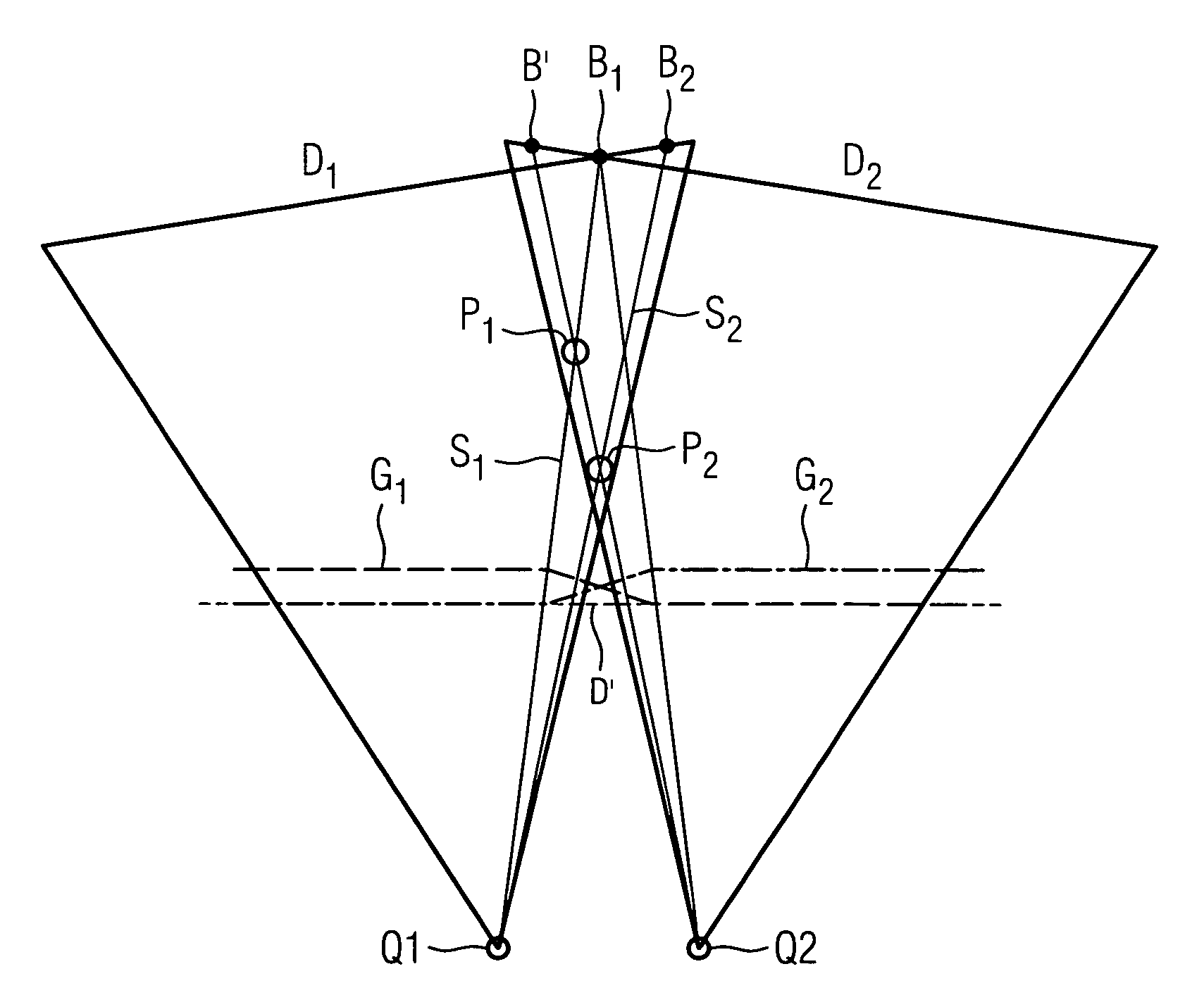
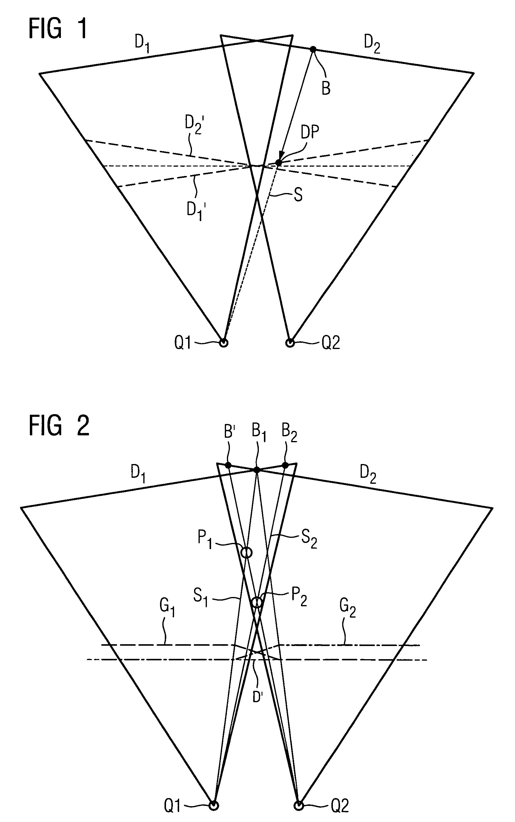
[0027]A 3D reconstruction of a body is generated by capturing a sequence of digital X-ray images. Two such digital X-ray projections are generated with a C-arm X-ray unit in a predefined position. The elements of the assembly comprising X-ray source and X-ray detector on the C-arm are rotated relative to each other, with the C-arm X-ray unit in a predefined position, between the capture of the first projection of the pair of projections and the second projection of the pair of projections. It is envisaged that the X-ray source remains in the same position. In practice the X-ray source tends to change position at least slightly. In FIG. 1 the position of the X-ray source for the first image is labeled Q1 and the position of the X-ray source for the second image is labeled Q2. The course of the X-ray detector for the first projection is labeled D1 and the course of the X-ray detector for the second projection is labeled D2. The geometric course of the X-ray detector may be designated ...


PUM


Abstract

The invention relates to a method for generating a 3D reconstruction of an especially large body that cannot be captured by a single projection by capturing at least two projections, which together capture the body, at each of the positions taken up by a C-arm X-ray unit. Data from the two projections is projected onto a virtual detector and the data from the virtual detector is then used for the filtered back projection procedure. It is assumed here that the real source remains motionless and that only the detector moves. A virtual detector D1′ / D2′ is only used in order to carry out large scale filtering in the event that real sources Q1 and Q2 for the two projections do not coincide. A return is then made to two independent projections. These two independent projections are used separately in the filtered back projection procedure to generate the 3D reconstruction.

Description

CROSS REFERENCE TO RELATED APPLICATIONS[0001]This application claims priority of German application No. 10 2007 026 115.4 filed Jun. 5, 2007, which is incorporated by reference herein in its entirety.FIELD OF THE INVENTION[0002]The invention relates to a method for generating a 3D reconstruction of a body.BACKGROUND OF THE INVENTION[0003]A 3D reconstruction is a data set in which individual volume elements (voxels) of a body are assigned numerical values (gray scale values). The compound view provides information about the structure of the body. 3D reconstructions are usually generated by capturing a sequence of two-dimensional images (projections) from different angles. The different angles are created by rotating—that is to say progressively changing the position of—a C-arm X-ray unit on which are mounted an X-ray source and an X-ray detector. Each projection (i.e. each image captured) is then back-projected in three dimensions. It is usually assumed in this method that the X-ray ...

Claims


Application Information

Patent Timeline
Patent Type & Authority Patents(United States)
IPC IPC(8): A61B6/00
CPCG01N23/046G06T11/006A61B6/03G01N2223/419G06T2211/421G06T2211/432
Inventor BRUNNER, THOMASHEIGL, BENNOKUNZE, HOLGERVOGT, FLORIAN
Owner SIEMENS HEALTHCARE GMBH
Why Eureka
Try Eureka