Multi-leaf collimator

a collimator and multi-leaf technology, applied in the field of multi-leaf collimators, can solve problems such as the patient's symptoms being alleled

Active Publication Date: 2010-06-22
ELEKTA AB
View PDF4 Cites 34 Cited by
  • Summary
  • Abstract
  • Description
  • Claims
  • Application Information

AI Technical Summary

Problems solved by technology

This adversely affects the tumour cells, causing an alleviation of the patient's symptoms.

Method used


Image

  • Multi-leaf collimator
  • Multi-leaf collimator
  • Multi-leaf collimator

Examples


Embodiment Construction

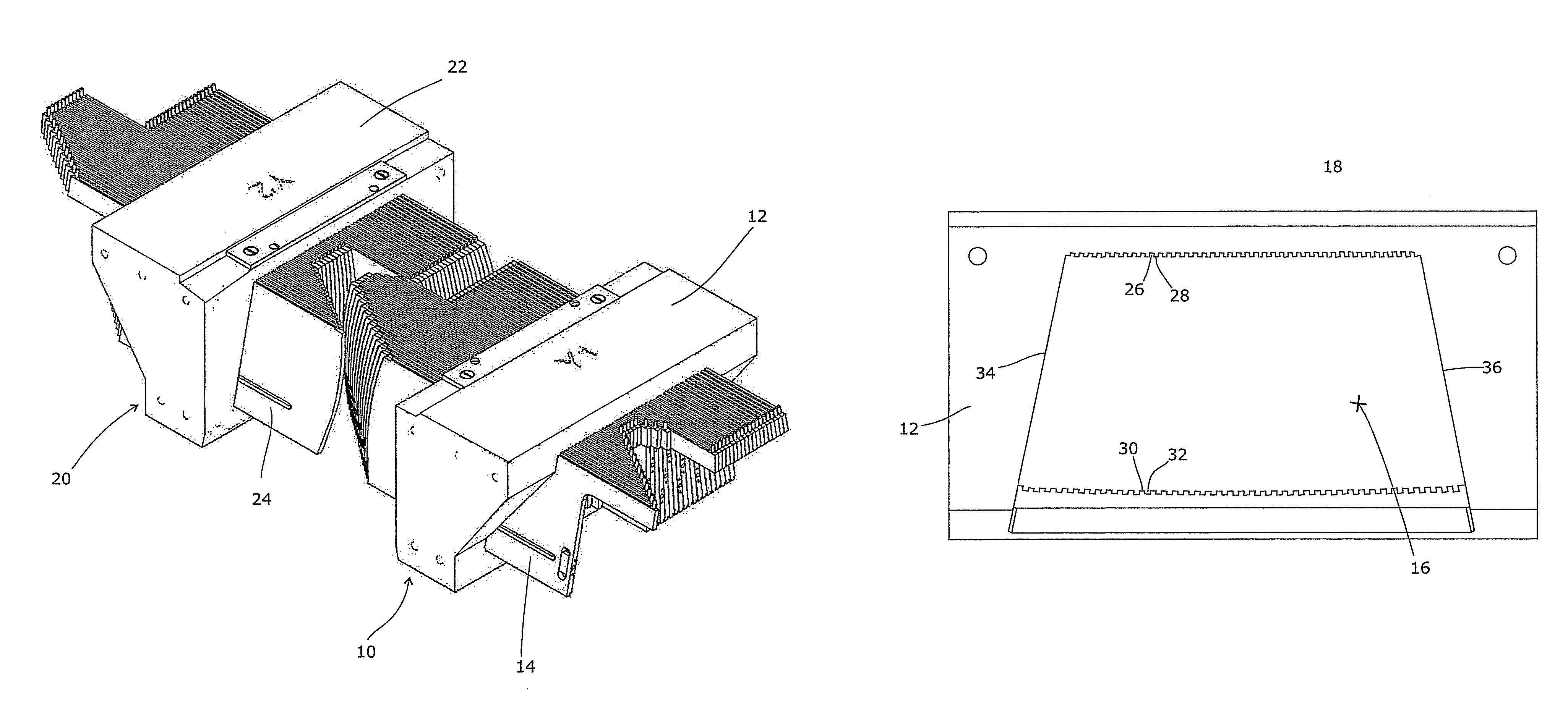
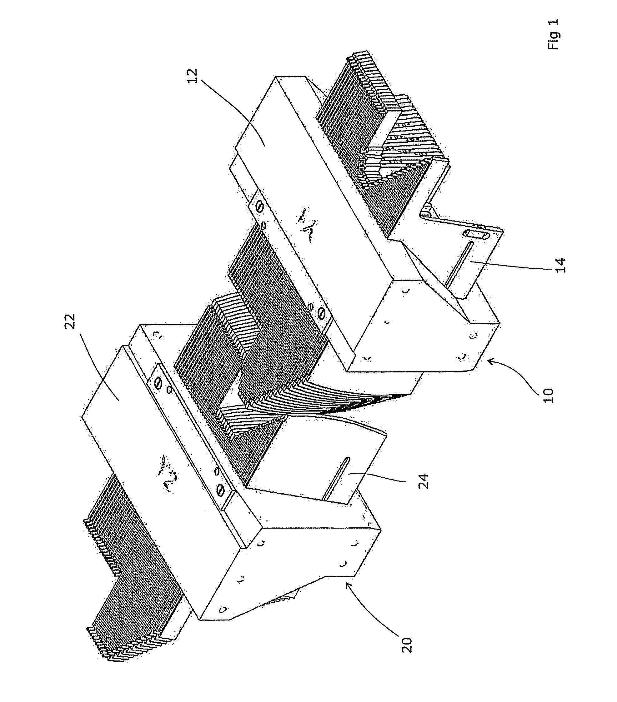
[0020]In this description the terms “up” and “down” refer to directions relative to the general disposition of the leaf or leaves of the multi-leaf collimator (MLC). Usually, the rest position for the radiation source of a typical oncology device is at the top of its rotational sweep, and therefore the conventional view of a radiotherapy head is with the beam travelling vertically downward. The leaves will thus be aligned in a generally vertical direction, with their long axis arranged horizontally.

[0021]As the radiation head rotates around a patient, as is commonly done in order to irradiate the tumour from a variety of directions and thereby minimise the dose that is applied to healthy tissue, the absolute orientation of the leaves (etc) will of course change, relative to a fixed frame of reference such as the room in which the apparatus is located. However, regardless of the actual orientation of the MLC and its leaves, in this description “up” is intended to mean a direction tow...


PUM


Abstract

A multi-leaf collimator for use in a radiotherapeutic apparatus comprises a plurality of elongate narrow leaves arranged side-by side and supported in a frame, the frame having upper and lower formations for guiding each leaf into which extend ridges on the upper and lower edges of the leaves, thereby to allow the leaves to move in a longitudinal direction, the upper and lower formations being aligned so that the sides of the leaves when fitted are at a non-zero angle to the beam direction, the upper and lower ridges being located on the upper and lower edges of the leaves so that a line joining their centres is at a non-zero angle to the sides of the leaf, tilted relative to the sides in a sense opposite to that of the beam. An outer face of the upper and / or lower ridges can be aligned with a side face of the leaf, for ease of manufacture. A radiotherapeutic apparatus is also disclosed, comprising a source of radiation and a multi-leaf collimator for shaping the radiation emitted by the source, the multi-leaf collimator being as set out above.

Description

CROSS-REFERENCE TO RELATED APPLICATION[0001]The present application claims priority of British patent application Serial No. 0802762.5, filed Feb. 15, 2008, and published in English the content of which is hereby incorporated by reference in its entirety.FIELD OF THE INVENTION[0002]The present invention relates to a multi-leaf collimator.BACKGROUND ART[0003]External Beam Radiotherapy involves the production of a beam of ionising radiation, usually x-rays or a beam of electrons or other sub-atomic particles, which is then directed towards a cancerous region of the patient. This adversely affects the tumour cells, causing an alleviation of the patient's symptoms. Generally, it is preferred to delimit the radiation beam so that the dose is maximised in the tumour cells and minimised in healthy cells of the patient, as this improves the efficiency of treatment and reduces the side effects suffered by a patient. A variety of methods of doing so have evolved.[0004]One principal component ...

Claims


Application Information

Patent Timeline
Patent Type & Authority Patents(United States)
IPC IPC(8): G21K1/04
CPCA61N5/1042A61B6/08A61N5/10A61N5/103G21K1/02G21K1/04G21K5/04
Inventor BOURNE, DUNCAN NEIL
Owner ELEKTA AB
Why Eureka
Try Eureka