Autonomous vehicle and planar obstacle recognition method

a technology of autonomous vehicles and planar obstacles, applied in the field of autonomous vehicles, can solve the problems of inability to recognize the planar obstacle having apertures, inaccurately, and complicated calculation process, and achieve the effect of increasing the moving speed of the autonomous vehicle, moving safely, and effective autonomous travel

Inactive Publication Date: 2010-06-22
MATSUSHITA ELECTRIC WORKS LTD
View PDF4 Cites 49 Cited by
  • Summary
  • Abstract
  • Description
  • Claims
  • Application Information

AI Technical Summary

Benefits of technology

[0004]The present invention is conceived to solve the above mentioned problems and to provide an autonomous vehicle which can autonomously move effectively and safely by recognizing a planar obstacle, especially a location of a planar obstacle having apertures by simple steps precisely, and to provide a planar obstacle recognition method suitable for the autonomous vehicle.
[0011]With such a configuration, when each length of the continuing element vectors is equal to or shorter than the first predetermined length, the deflection angle of one element vector with respect to another continuing element vector is equal to or smaller than the first predetermined angle, and the integrated value of the deflection angles is equal to or smaller than the second predetermined value, it can be regarded that the scanning points used for forming the element vectors are disposed on the same obstacle. Furthermore, when the length of the scanning segment vector formed by composition of the element vectors is equal to or longer than the second predetermined length, it can be regarded that the obstacle is a planar obstacle. The scanning segment vector represents a position, an orientation and a size of the planar obstacle, so that the self location recognition unit can be specified the self location of the autonomous vehicle on a map precisely based on a distance and a direction to the planar obstacle, and thereby the autonomous vehicle can move safely by avoiding the planar obstacle identified by the scanning segment vector when the autonomous vehicle performs the autonomous travel. Still furthermore, the recognition of the planar obstacle can be performed by relatively simple processes such as acquirement of the scanning points, formation of the element vectors, selection of the element vectors, formation of the scanning segment vector and comparison of the scanning segment vector. Thus, it is possible to recognize the planar obstacle faster in comparison with the conventional method. Consequently, effective autonomous travel can be realized by increasing the moving speed of the autonomous vehicle.

Problems solved by technology

Thus, the calculation process becomes complex and requires a long time.
In addition, according to the conventional planar obstacle recognition method, when the planar obstacle has apertures like a meshed or grated fence, reflected waves from an object disposed behind the planar obstacle are received, so that it is difficult to recognize the planar obstacle having apertures, accurately.
Therefore, no method which can recognize the planar obstacle having apertures is put into practical use as the planar obstacle recognition method which is suitable for autonomous vehicle.

Method used


Image

  • Autonomous vehicle and planar obstacle recognition method
  • Autonomous vehicle and planar obstacle recognition method
  • Autonomous vehicle and planar obstacle recognition method

Examples


Embodiment Construction

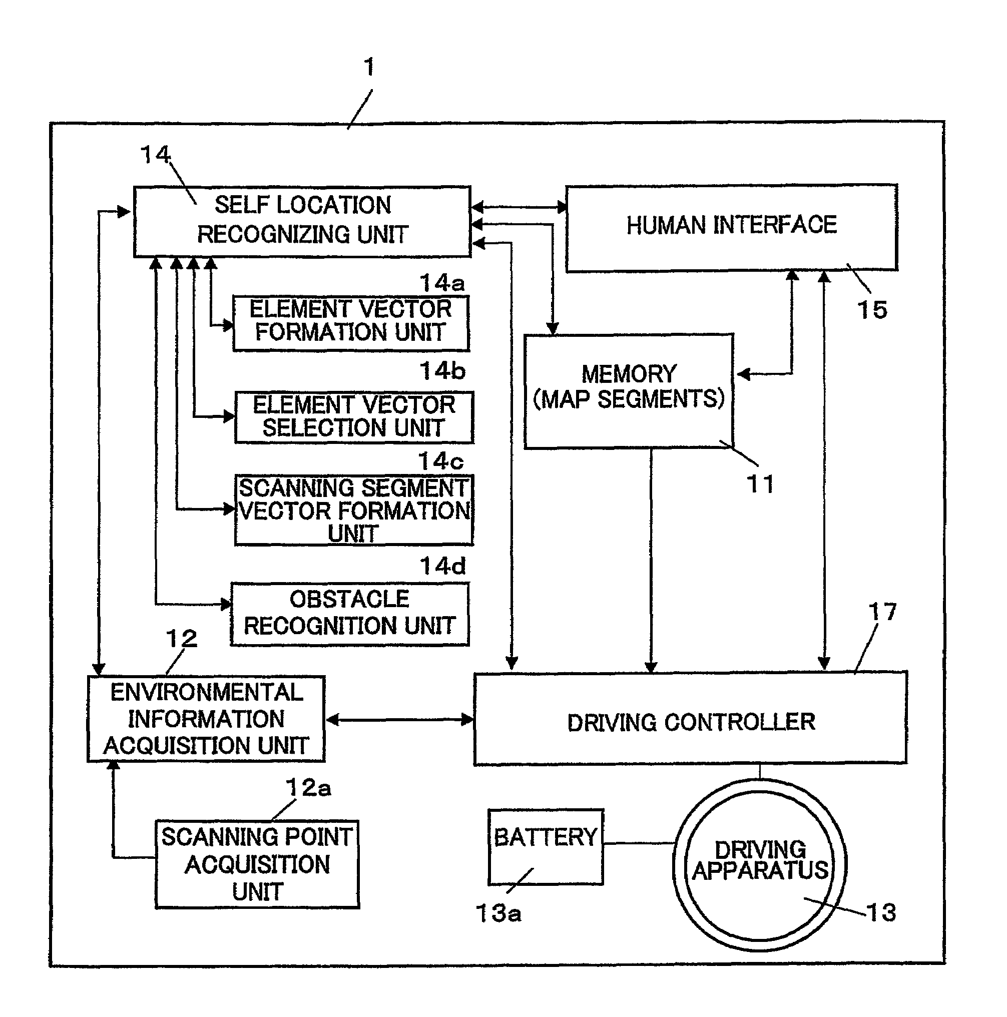
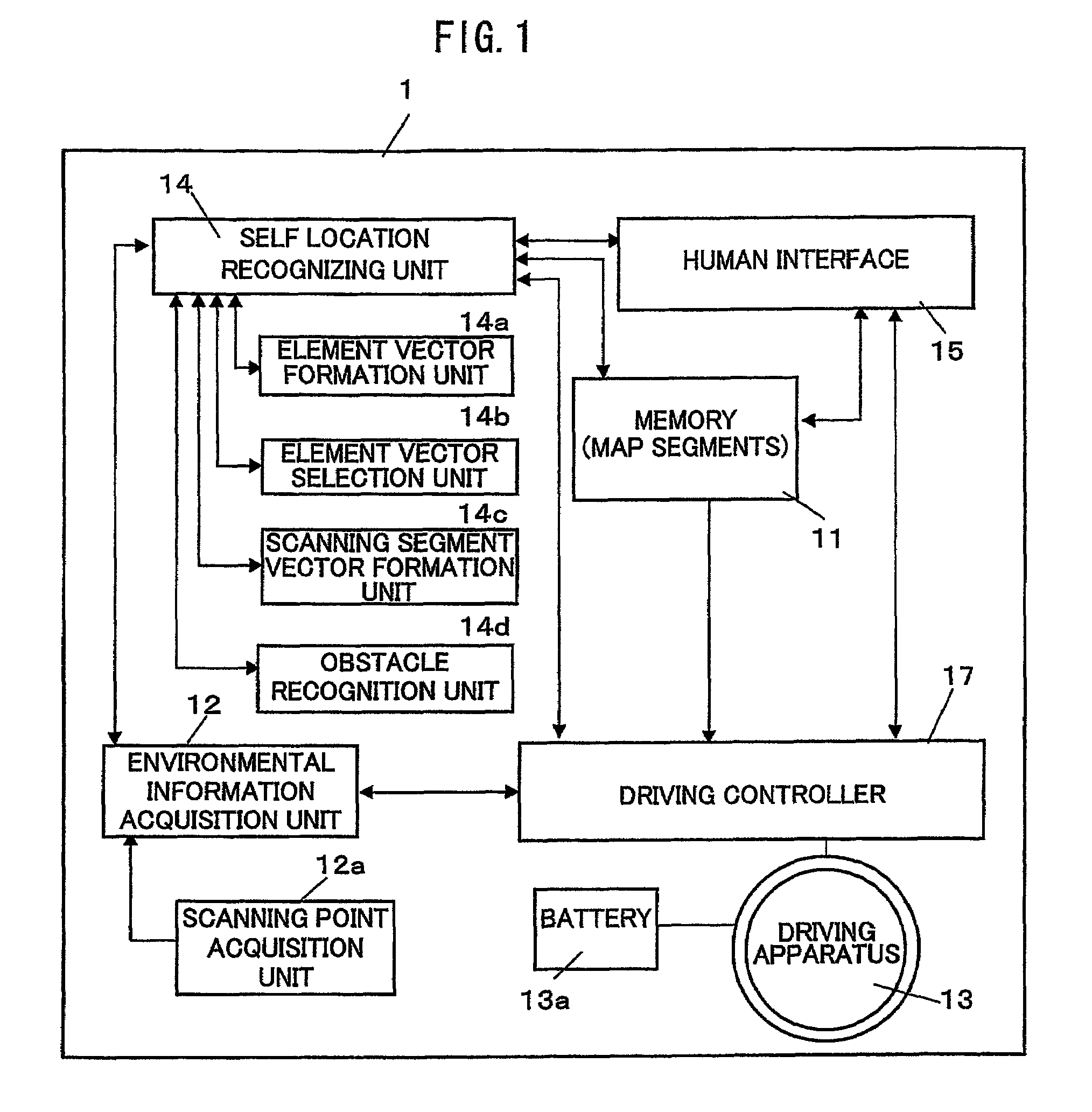
[0043]An autonomous vehicle and a planar obstacle recognition method suitable for the autonomous vehicle in accordance with an embodiment of the present invention are described with reference to the figures. FIG. 1 shows a block constitution of the autonomous vehicle 1 of the present invention. The autonomous vehicle 1 is comprised of a memory 11 for memorizing map information of an operation area thereof and various parameters used for driving thereof, an environmental information acquisition unit 12 for acquiring environmental information used for recognizing location of an obstacle and self location, a driving apparatus 13 for driving the autonomous vehicle 1, a self location recognition unit 14 for recognizing the self location of the autonomous vehicle 1 by referring the environmental information acquired by the environmental information acquisition unit 12 with the map information memorized in the memory 11, a human interface 15 used for inputting a destination in the operatio...


PUM


Abstract

In an autonomous vehicle, position of a planar obstacle such as a wall or a fence having apertures is determined. A horizontal plane is scanned with a laser range tinder so as to acquire positional coordinates of a plurality of scanning points. An element vector is formed with each two scanning points so that one acquired former is used as a start point and the other acquired later as an end point of the vector. A plurality of continuous element vectors which satisfy predetermined conditions is selected among the element vectors, and a scanning segment vector is formed by composition of the selected element vectors. When a length of the scanning segment vector is equal to or longer than a predetermined length, it is possible to recognize that a planar obstacle exists along the scanning segment vector.

Description

TECHNICAL FIELD[0001]The present invention relates to an autonomous vehicle, and especially relates to a planar obstacle recognition method installed in the autonomous vehicle and suitable for autonomous travel.BACKGROUND ART[0002]Conventionally, a method for recognizing positions on a surface of a wall (planar obstacle) is known from the document (Li Zhang & Bijoy K. Ghosh, “Line Segment Based Map Building and Localization Using 2D Laser Range finder”, IEEE Int. Conf. On Robotics & Automation, pp. 2538-2543, 2000). In the conventional method, a horizontal plane is scanned at an every constant angle or a constant distance with using a laser radar so that a group of scanning points each distributed in two-dimensional surface is acquired by receiving reflected waves from an object. A plurality scanning points are selected with specific assumptions from the group of the scanning points, and an aggregation of segments is formed by coupling the selected scanning points. The wall distribu...

Claims


Application Information

Patent Timeline
Patent Type & Authority Patents(United States)
IPC IPC(8): G05D1/02
CPCG05D1/024G05D1/0255G06T7/0042G05D1/0274G05D1/0257G05D2201/0216G06T7/73
Inventor SAKAI, TATSUNISHIMURA, DAISUKE
Owner MATSUSHITA ELECTRIC WORKS LTD
Why Eureka
Try Eureka