
Checking the robustness of a model of a physical system

a physical system and robustness technology, applied in the direction of machines/engines, electrical control, instruments, etc., can solve the problems of system failure, major new engineering costs, hardware and software reverse engineering, etc., to reduce the cost of developing, high quality, and good safety

Active Publication Date: 2010-06-22
HISPANO SUIZA SA
View PDF10 Cites 6 Cited by
  • Summary
  • Abstract
  • Description
  • Claims
  • Application Information

AI Technical Summary

Benefits of technology

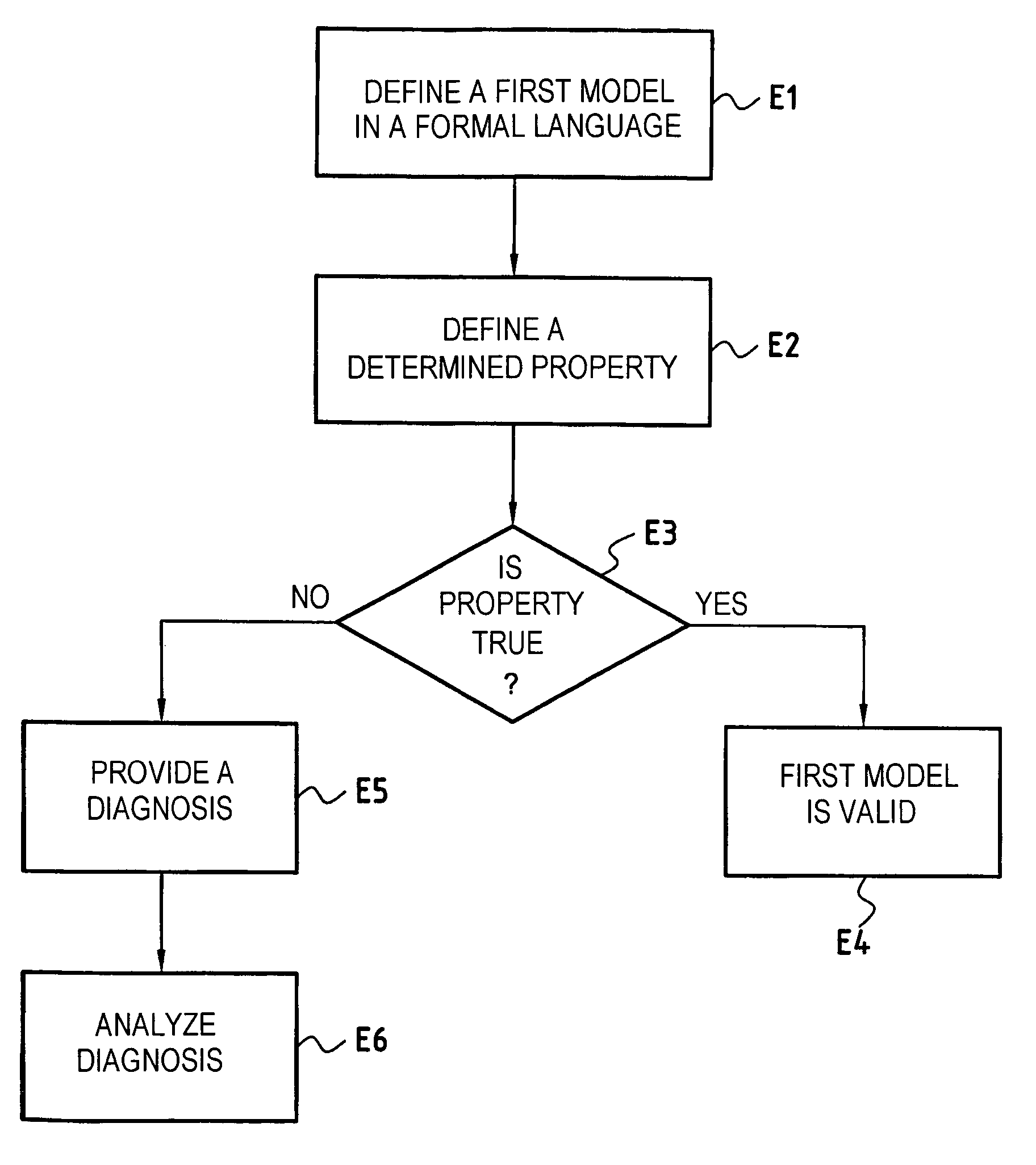
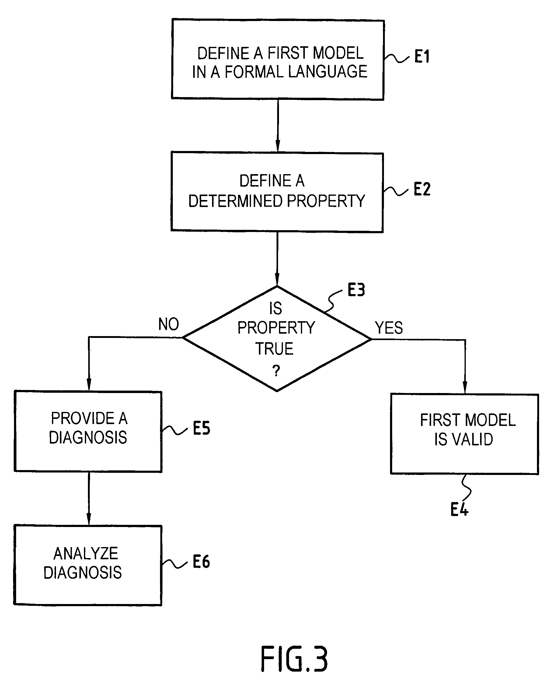
"The present invention proposes a method for verifying the robustness of a model of an electronic system when faced with faults. This is achieved by creating a second model of the system enriched by a fault injection mechanism, and using formal proof means to search automatically for a combination of injected faults and / or input values that causes a determined property to fail. This method makes it possible to design a system that is robust in the face of faults, reducing the cost of developing it, and also makes it possible to make a system that is of very high quality and good safety by exhaustively verifying any conceivable fault or sequence of faults. The fault injection mechanism includes injecting at least one fault into the second model via a fault input interface, and the description in the formal language of the effect(s) of the fault on the function or behavior of each of the components of the electronic system. The combination of faults that causes the determined property to fail is considered as being a scenario that can enable the model of the physical system to be corrected to make it more robust. The determined property expresses a state or a behavior of the physical system, and it may be a safety property of the system."

Problems solved by technology

Unfortunately, it is practically impossible for a model to take account of all eventualities.
It often happens that some particular scenario is forgotten, or that a sequential logic error is made, such that some sequence or particular combination of faults can still cause the system to fail.
However, on discovering a defect in a real system, it is necessary to redesign the system, which implies major new engineering costs, hardware and software reverse engineering, and a major loss of time.

Method used


Image

  • Checking the robustness of a model of a physical system
  • Checking the robustness of a model of a physical system
  • Checking the robustness of a model of a physical system

Examples


Embodiment Construction

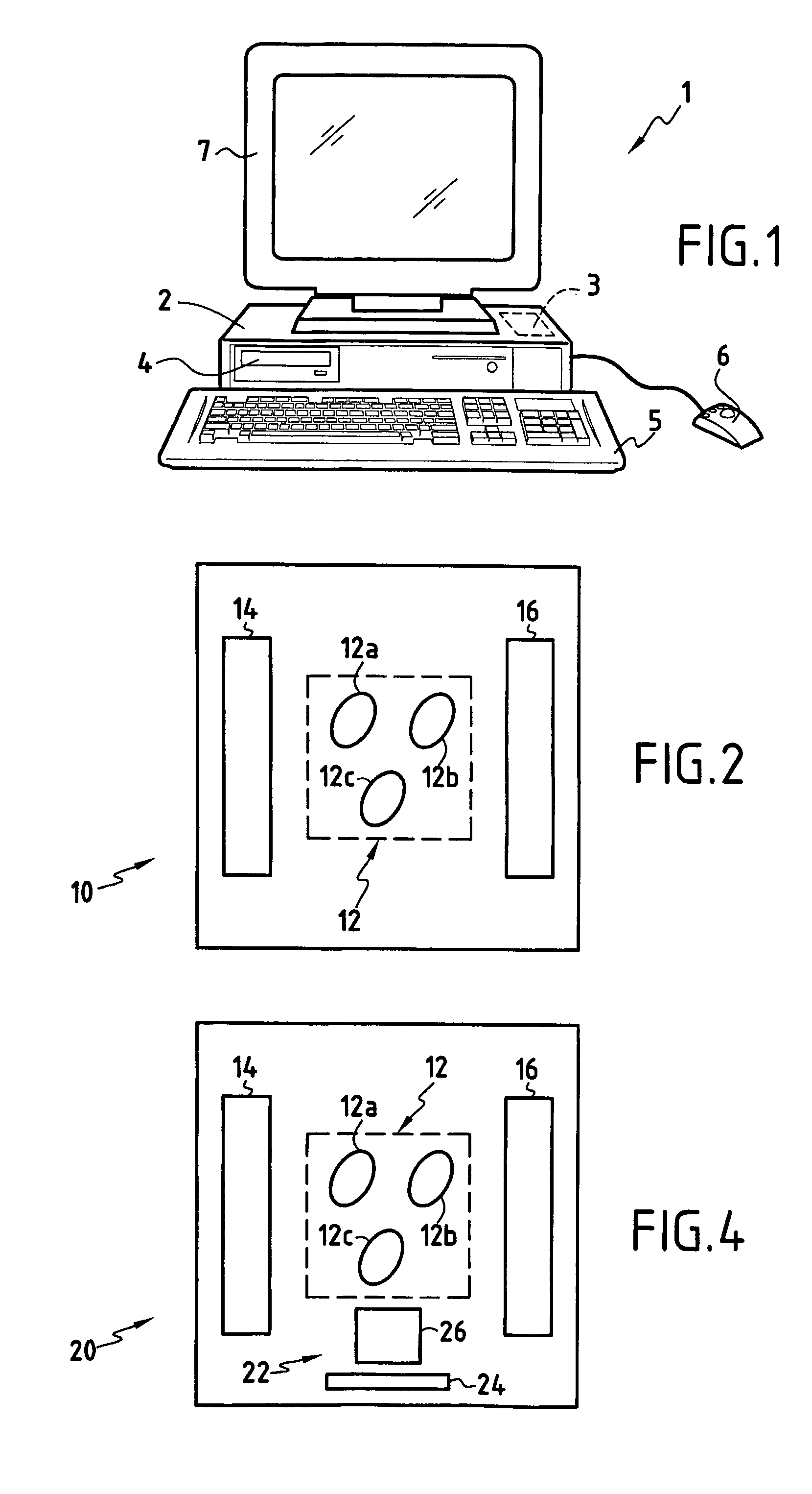
[0030]FIG. 1 shows a system that can be used for modeling a physical system. The system comprises a workstation or computer 1 used for running a computer program designed to implement the method of the invention.

[0031]The computer 1 comprises the hardware means that are conventionally to be found with this type of apparatus. More particularly, the computer comprises a central unit 2 which executes sequences of instructions of the program in accordance with the method of the invention, a central memory 3 which stores data and the program that is being executed, digital data storage media (hard disk, compact disk (CD) 4, floppy disk, . . . ) for long-term storage of the data and programs in use, input peripherals (keyboard 5, mouse 6, . . . ), and output peripherals (screen 7, printer, . . . ) for enabling the model of the physical system to be viewed.

[0032]In accordance with the invention, FIG. 2 shows a first model 10 for designing a physical system. The physical system may, for exa...


PUM


Abstract

The invention provides a system and a method for verifying the robustness of a model of a physical system, the method comprising the following steps: defining a first model of the physical system comprising a set of components and at least one input interface for inserting input values, said first model being defined in a formal language describing the behavior and the function of each of said components; defining in the formal language a determined property that must be satisfied by the model of the physical system; defining in the formal language a second model corresponding to the first model and enriched by a fault injection mechanism; and using formal proof means to search automatically for a combination of injected faults and / or input values that causes said determined property to fail.

Description

FIELD OF THE INVENTION[0001]The present invention relates to the field of checking the robustness of a model of a physical system in the face of faults appearing.PRIOR ART[0002]In numerous industries, such as the aviation or space industries, it is common practice to rely on models of systems. For example, a model is designed of a physical system that is to accomplish some given mission, and the model is used in order to evaluate interference between the system and its environment. This is done using either hardware means or software means.[0003]In particular, fault detection logic, reconfiguration logic, and component redundancy are used in order to make a system tolerant to faults.[0004]Unfortunately, it is practically impossible for a model to take account of all eventualities. It often happens that some particular scenario is forgotten, or that a sequential logic error is made, such that some sequence or particular combination of faults can still cause the system to fail.[0005]I...

Claims


Application Information

Patent Timeline
Patent Type & Authority Patents(United States)
IPC IPC(8): G06F9/45G06F17/50F02C9/00F02D45/00G01R31/00G06F11/26
CPCG06F17/504G06F30/3323
Inventor GRANIER, HUGUESBREGAINT, CHRISTIANTONNELIER, PHILIPPECROIX MARIE, MARC
Owner HISPANO SUIZA SA
Learn More