Rotary draw tube bender

a rotary draw tube and bending machine technology, applied in the direction of manufacturing tools, metal-working apparatus, shaping tools, etc., can solve the problems of improper rounded or flattening of the bend surface, workpiece slip through the bending die hook,

Active Publication Date: 2010-06-29
JPW IND
View PDF3 Cites 9 Cited by
  • Summary
  • Abstract
  • Description
  • Claims
  • Application Information

AI Technical Summary

Benefits of technology

[0019]The present invention relates to a rotary draw bending machine and a process of using that machine to bend workpieces such as tubes or pipes into precise bends. The bending machine has a spindle holding a bending die, and a radial arm holding a counter-die. The spindle and arm are simultaneously rotated in opposite directions by the dual hydraulic drive. Each rotates half the desired bend angle. The desired bend angle is set by a dial with a triggering groove that are rotated relative to a fixed limit switch. The hydraulic drive moves the machine between a home positioned at 0° and the desired bend angle position. The machine is controlled by an electro-hydraulic control system with foot pedal controls. The radial arm has an alignment mechanism formed by a track that slidingly receives the counter-die assembly. A ratchet mechanism incrementally aligns the counter-die with the bending die. Ratchet teeth allow incremental advancement of the counter-die when aligning it with its bending die to accurately set the proper gap between the counter-die and bending die. The ratchet mechanism preferably includes a fine tuning device to provide an infinite range of adjustability for setting the die gap.
[0020]An advantage of the present tube bender is its die gap alignment mechanism. The alignment mechanism is located on the rotating arm and includes a slide track and ratchet mechanism. The alignment mechanism provides incremental, adjustable positioning of the counter-die relative to the bending die. The saw-tooth shape of its ratchet teeth and the tip shape of the ratchet arm allow forward sliding movement of the counter-die assembly, and selectively prevent rearward movement. This incremental sliding movement positions the counter-die near the bending die with a relatively small, but necessary, incremental gap between them. A gap of about ⅛ inch between the ends of the dies is common. This gap ensures that the counter-die properly holds and maintains contact with the tubular workpiece during the bending operation. The counter-die snuggly presses the workpiece, but not so tight as to cause undesired binding. An overly tight grip causes the workpiece to bind with the counter-die, which causes the workpiece to slip through the hook of the bending die. Too loose of a grip and the workpiece will disengage from the counter-die in the critical bend forming region, which results in an improperly rounded or flattened bend surface.

Problems solved by technology

An overly tight grip causes the workpiece to bind with the counter-die, which causes the workpiece to slip through the hook of the bending die.
Too loose of a grip and the workpiece will disengage from the counter-die in the critical bend forming region, which results in an improperly rounded or flattened bend surface.

Method used


Image

  • Rotary draw tube bender
  • Rotary draw tube bender
  • Rotary draw tube bender

Examples


Embodiment Construction

[0050]While this invention is susceptible of embodiment in many different forms, the drawings show and the specification describes in detail a preferred embodiment of the invention. It should be understood that the drawings and specification are to be considered an exemplification of the principles of the invention. They are not intended to limit the broad aspects of the invention to the embodiment illustrated.

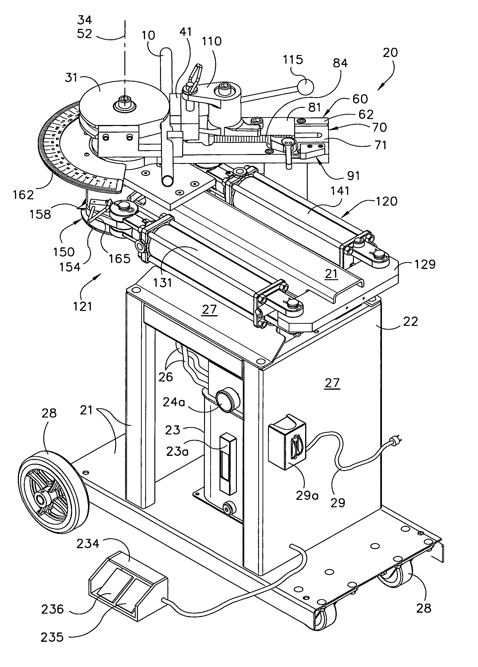
[0051]The present invention relates to a rotary draw tube bending machine generally designated by reference number 20 in FIG. 5. The bending machine 20 has a power operated, rotating drive spindle. The tube bending machine or tube bender 20 has a frame 21 that forms a lower shelf or cabinet 22 and two upper platforms. A hydraulic fluid reservoir 23 is located in the cabinet 22. The reservoir 23 includes a fluid level indicator 23a and a filter 23b. A conventional pump 24 is used to pressurize the fluid to about 2,200 to 2,500 pounds per square inch (psi), which is indicated by...


PUM


Abstract

The invention is a rotary draw bending machine and process for bending materials such as tubes or pipes into precise bends. A spindle holds a bending die, and a radial arm holds a counter-die. The spindle and arm are simultaneously rotated in opposite directions by a dual hydraulic drive controlled by an electro-hydraulic control system with foot pedal controls. The bend angle is preset by a protractor-like dial and limit switch mechanism. The radial arm has a slide track to align the counter-die with the bending die. The ratchet mechanism has teeth to allow incremental advancement of the counter-die when aligning it with its bending die to accurately set the gap between the dies. The machine is used with a wide variety of dies to bend a wide variety of workpiece diameters. The ratchet mechanism preferably includes a fine tuning device to provide an infinite range of alignment positions.

Description

CROSS REFERENCE TO RELATED APPLICATION[0001]This application is a Continuation of U.S. application Ser. No. 11 / 724,852 filed Mar. 16, 2007, now U.S. Pat. No. 7,380,430.TECHNICAL FIELD OF THE INVENTION[0002]This invention relates to a rotary draw tube bender with a rotating spindle and arm driven by a dual hydraulic drive via an electro-hydraulic control system with foot pedal controls, and aligned with a ratchet mechanism to incrementally and accurately set the gap between the bending die and counter-die.BACKGROUND OF THE INVENTION[0003]Many buildings, construction sites, manufacturing plants and machine shops require or use a significant quantity of bent tubes, pipes and rods to produce items such as hand rails, scaffolding, or fabricated metal products. A variety of conventional machines have been developed to facilitate the otherwise difficult task of bending of rigid metal tube or pipe into a desired shape. One type of tube bending machine is the rotary draw bender. This bending...

Claims


Application Information

Patent Timeline
Patent Type & Authority Patents(United States)
IPC IPC(8): B21D7/00B21D7/04
CPCB21D7/02
Inventor RUSCH, CHRISTOPHER J.
Owner JPW IND
Why Eureka
Try Eureka