Heat exchanger, intermediate heat exchanger, and regrigeration cycle

An intermediate heat exchanger and refrigeration cycle technology, applied in the direction of indirect heat exchangers, heat exchanger types, refrigerators, etc., can solve problems such as difficult bending processing, reduce heat transfer performance, increase flow resistance, etc., and achieve good bending performance , Improve heat transfer efficiency, improve the effect of heat transfer performance

Inactive Publication Date: 2007-06-06
RESONAC HOLDINGS CORPORATION
View PDF2 Cites 8 Cited by
  • Summary
  • Abstract
  • Description
  • Claims
  • Application Information

AI Technical Summary

Problems solved by technology

[0010] As for the heat exchangers disclosed in Patent Documents 1 and 2, although heat exchangers are generally formed by extrusion, it is difficult to form heat exchange tubes with a plurality of passages by extrusion, and leads to limitations. such as channel diameter and / or profile
This results in the formation of smaller diameter channels, thus increasing the resistance to flow, as well as increasing the thickness of the partitions (fins) between the channels, which reduces heat transfer and thus heat transfer performance
In addition, the entire tube is formed into a one-piece processed product, and the partitions (fins) between the passages are thick, so it is difficult to bend
For example, when such a heat exchanger is used in a refrigeration cycle for an air conditioner, it is impossible to form a shape corresponding to the shape of a limited installation space in an automobile, thereby reducing the degree of freedom in design
[0011] Furthermore, in the heat exchanger disclosed in Patent Document 3, since the inner tube is restrained by the outer tube, the external force acting on the outer tube can easily act on the inner tube, causing cracks to be generated on the curved outer side of the fins of the inner tube , resulting in reduced pressure resistance and durability
Therefore, this heat exchanger is also not suitable for bending

Method used


Image

  • Heat exchanger, intermediate heat exchanger, and regrigeration cycle
  • Heat exchanger, intermediate heat exchanger, and regrigeration cycle
  • Heat exchanger, intermediate heat exchanger, and regrigeration cycle

Examples


example 1

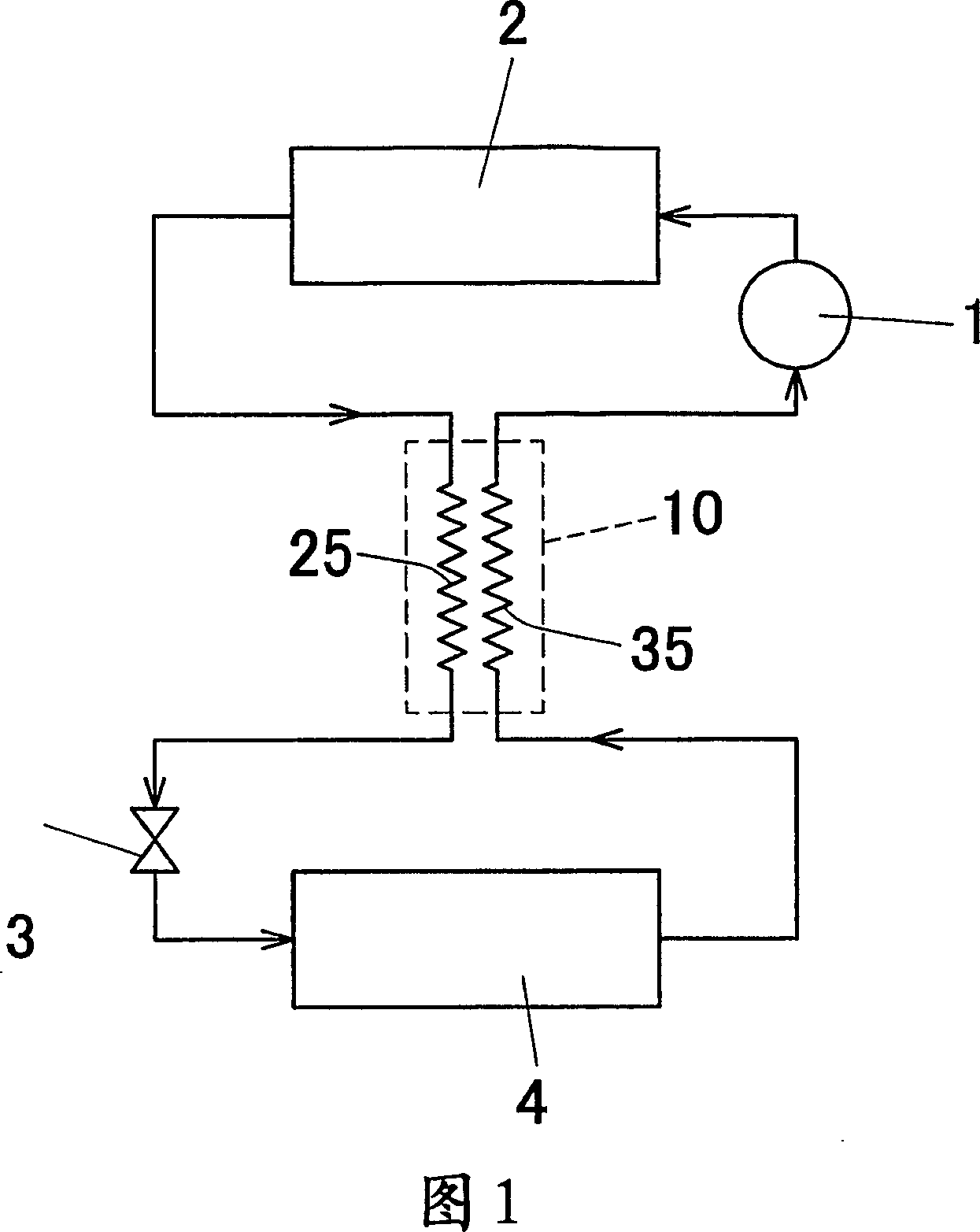
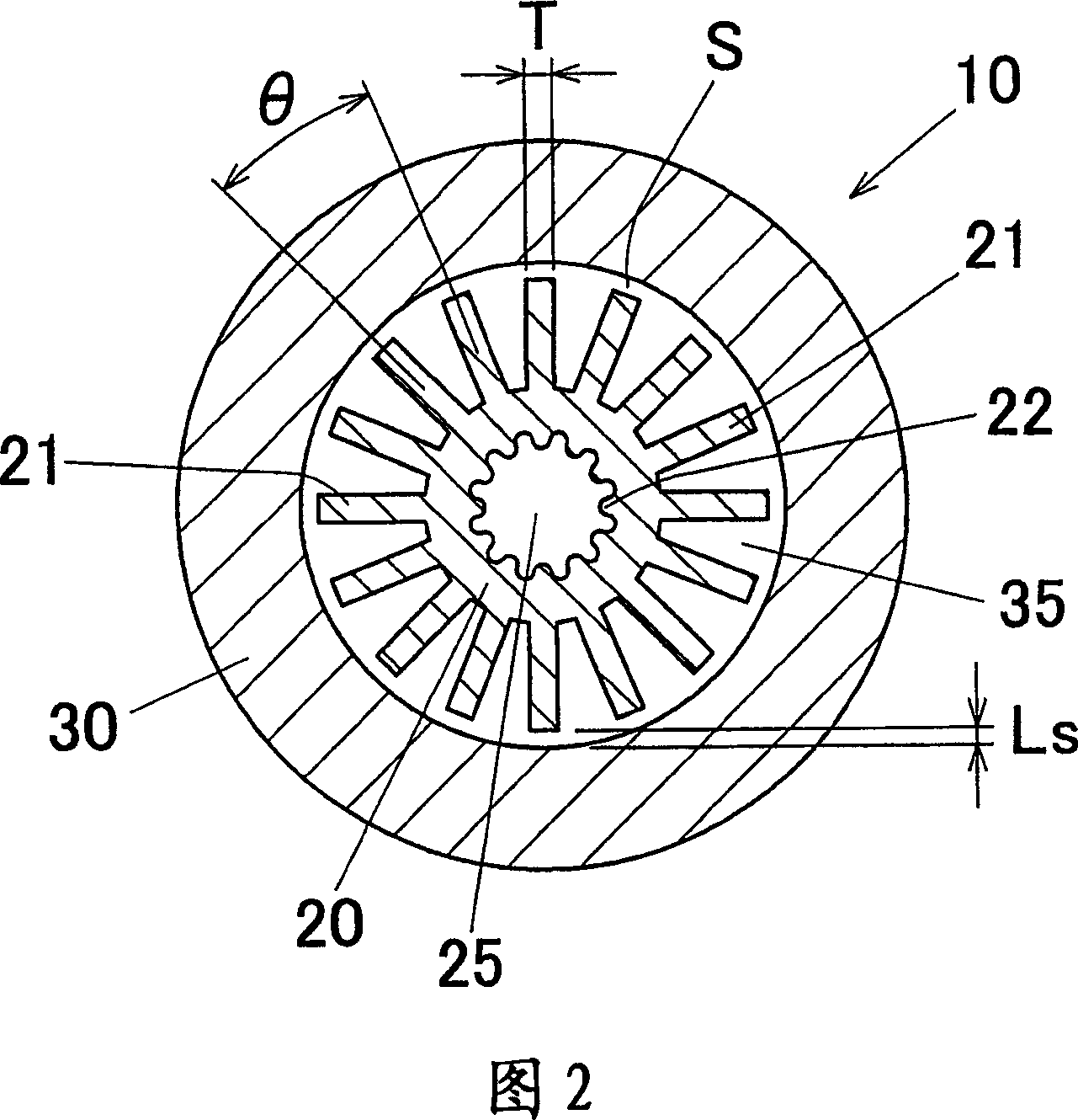
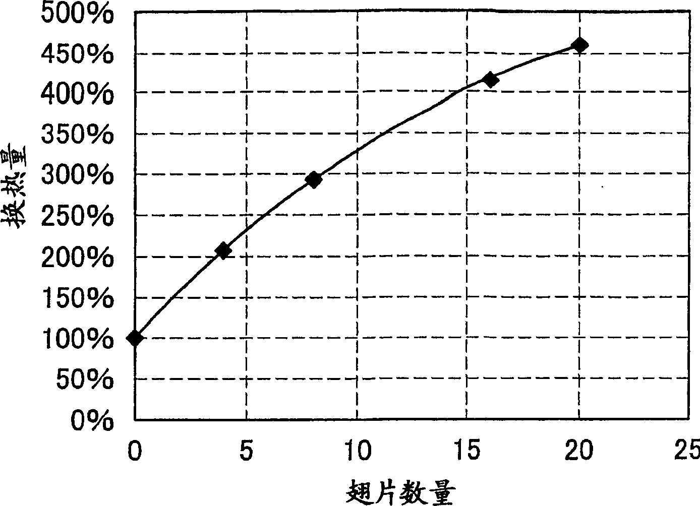
[0097] In the automotive air-conditioning refrigeration system using the intermediate heat exchanger 10 shown in Figure 1, in which the inner tube 20 with fins 21 on the outer wall is inserted into the outer tube 30, the number of fins is different The exchange heat of each intermediate heat exchanger 10 is obtained by computer simulation. The results are shown in Table 1, where the heat transfer is expressed in % (when the number of fins is 0, it is 100%).

[0098] The conditions are set as follows: the length of the intermediate heat exchanger (the length of the outer tube) is set to 500 mm, the outer diameter of the outer tube 30 is set to 21.0 mm, the inner diameter of the outer tube 30 is set to 15.0 mm, and the inner tube 20 includes outer fins 21 The outer diameter of the inner tube 20 is set to 14.0mm, the outer diameter of the inner tube 20 excluding the outer fin 21 is set to 7.0mm, the inner diameter of the tubular part of the inner tube 20 excluding the inner fin 2...

example 2

[0102] Under the same conditions as Example 1, the flow resistance of the low-pressure side refrigerant heat exchange channel (the channel between the inner tube and the outer tube) of each heat exchanger with different numbers of fins was obtained by computer simulation. The results are shown in Table 1, where the flow resistance is expressed in % (when the number of fins is 0, it is 100%).

[0103] Table 2

[0104]

[0105] As shown in Table 1, as the number of fins increases, the heat transfer performance increases, and thus the amount of heat transfer increases. On the other hand, as shown in Table 2, as the number of fins increases, the flow resistance increases and thus the heat transfer decreases. Considering comprehensively, when the number of fins is 13-18, the flow resistance can be controlled within a certain range, and proper heat transfer performance can be obtained. In particular, when the number of fins is 15 to 17, the flow resistance is sufficiently restric...


PUM


Abstract

A heat exchanger includes an outer tube 30 and an inner tube 20 having a plurality of fins 21 formed on an external periphery of the inner tube 20 and disposed in the outer tube 30. The heat exchanger is designed to exchange heat between first fluid passing through the inner tube and second fluid passing in between the outer tube and the inner tube. A gap S is formed between an internal periphery of the outer tube 30 and a tip end of each of the plurality of fins 21 of the inner tube 20. This structure can improve the heat exchanging performance and provide a heat exchanger excellent in vending workability.

Description

[0001] This application claims the benefit of Japanese Patent Application No. 2004-230778, filed August 6, 2004, and U.S. Provisional Application S.N. 60 / 600,357, filed August 11, 2004, the entire disclosures of which are incorporated as It is hereby incorporated by reference in its entirety. [0002] Cross References to Related Applications [0003] This application is an application filed pursuant to 35 U.S.C. §111(a) and required under 35 U.S.C. §119(e)(1) of the U.S. Provisional Filed August 11, 2004 under 35 U.S.C. §111(b) Filing date benefits for application No. 60 / 600,357. technical field [0004] The present invention relates to a refrigeration cycle as used, for example, in a refrigeration cycle of a motor vehicle air conditioner, and also to an intermediate heat exchanger and a heat exchanger for this cycle. Background technique [0005] In most traditional vapor compression refrigeration cycles, Freon series refrigerants are used. However, in recent years there...

Claims


Application Information

Patent Timeline
Patent Type & Authority Applications(China)
IPC IPC(8): F28D7/10F25B1/00F25B39/00F28F1/42
CPCF28F1/422F28F1/42F28D7/106F25B2309/061F25B40/00
Inventor 武幸一郎一柳茂治
Owner RESONAC HOLDINGS CORPORATION
Why Eureka
Try Eureka