Optical scanner

a scanner and optical technology, applied in the field of optical scanners, can solve the problems of reducing image resolution and no stable beam spot on the objective surface, and achieve the effect of high optical performan

Inactive Publication Date: 2005-02-01
DAINIPPON SCREEN MTG CO LTD
View PDF7 Cites 7 Cited by
  • Summary
  • Abstract
  • Description
  • Claims
  • Application Information

AI Technical Summary

Benefits of technology

(1) to provide a compact optical scanner by implementing an f-θ lens having a small total length L and...

Problems solved by technology

The imaging position of the light beam varies with change of the oscillation wavelength due to chromatic aberration of the f-θ lens 104, to result in such a problem that no stable beam spot is obtained on the objective surface 106 and reso...

Method used


Image

  • Optical scanner
  • Optical scanner
  • Optical scanner

Examples


first preferred embodiment

An f-θ lens 6 according to a first preferred embodiment of the present invention is designed to be preferable as to a light beam having a working wave range of a central wavelength of 405 nm, a maximum wavelength of 410 nm and a minimum wavelength of 400 nm. In order to optimize optical performance with respect to this working wave range in particular, the f-θ lens 6 preferably satisfies the following conditional expressions (2A), (4A), (5A) and (6A): 0.04≤r1r4≤0.17(2⁢A)0.48≤v1v2≤0.58(4⁢A)0.42≤v4v3≤0.47(5A)0.24≤f1f≤0.32(6A)

first example

An f-θ lens 6 according to a first example of this embodiment is now described. FIG. 3 is a schematic sectional view of the f-θ lens 6 according to the first example. Table 1 shows the focal distance f, the F-number and the total angle θ of view of the f-θ lens 6 according to the first example and a working wave range of a laser beam oscillated in a light source 1.

TABLE 1F-NumberF / 41Focal Distance (f)f = 693.5 mmTotal Angle of View (θ)45.44°Central Wavelength (λ0)λ0 = 405 nmUpper Limit of Working Wave Range (λmax)λmax = 410 nmLower Limit of Working Wave Range (λmin)λmin = 400 nm

Table 2 shows values indicating optical characteristics of the f-θ lens 6 according to the first example.

TABLE 2ir(i)d(i)nd(i)νd(i)1−120.49.81.6258835.72−46.755.01.6073856.83∞17.44−2150.015.31.6030065.55−66.647.01.6476933.86−181.00.57−1172.010.01.6516058.58−214.7

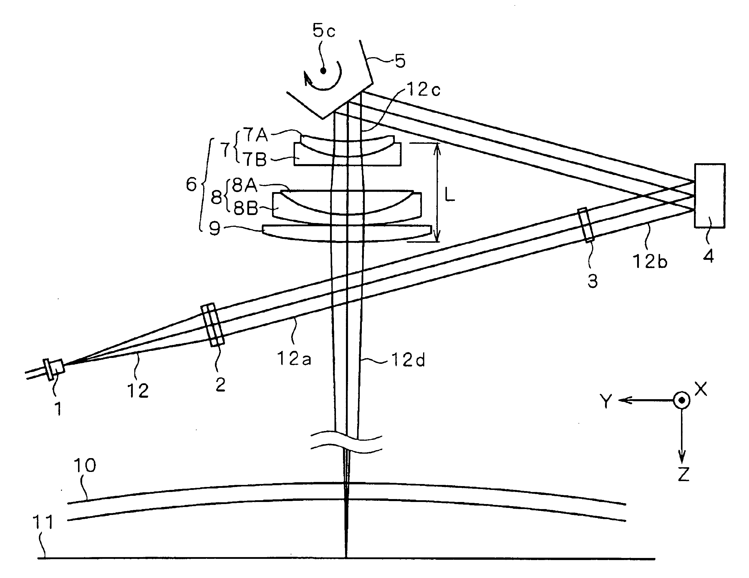
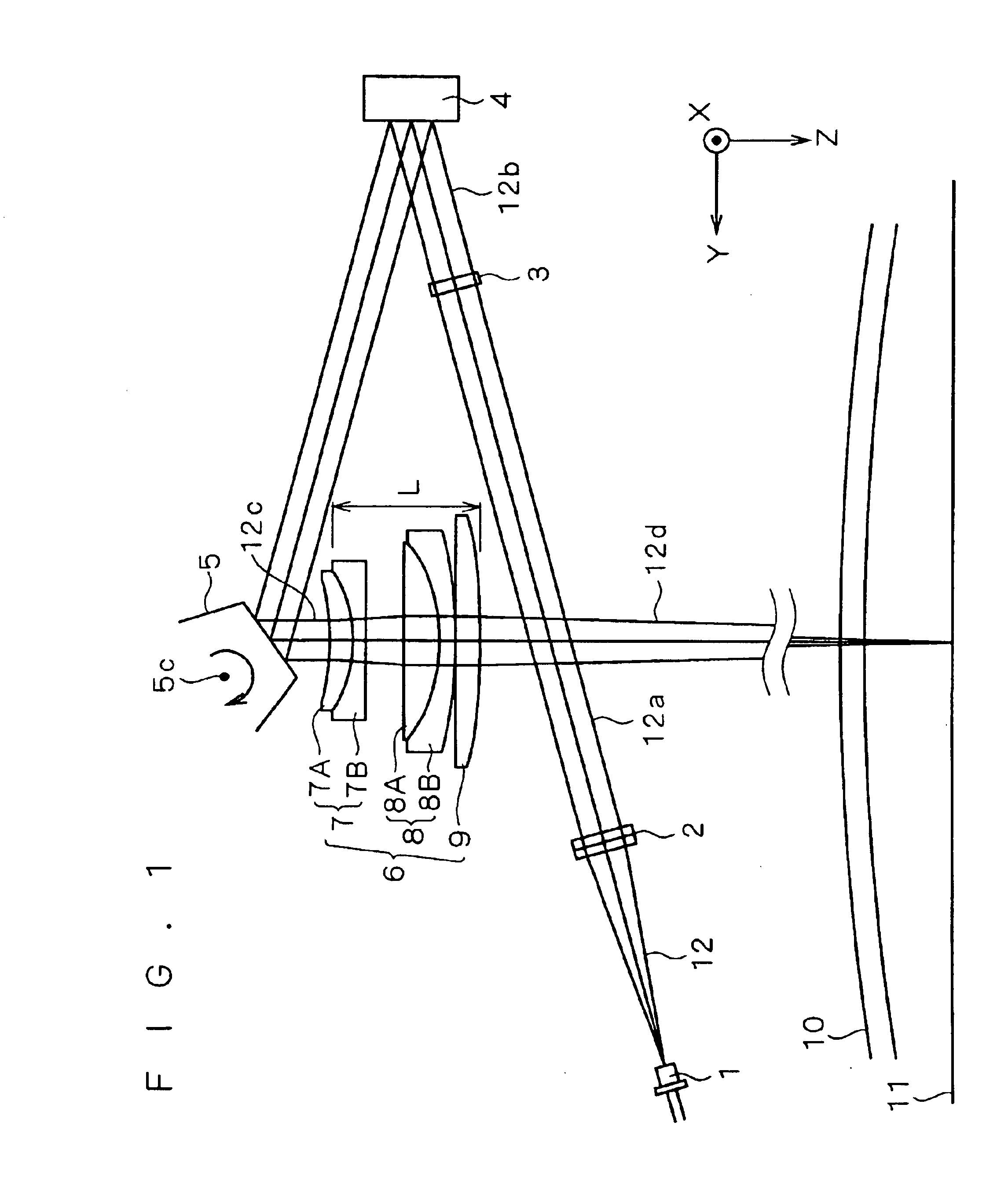
As shown in FIG. 3, first to fifth lenses 7A to 9 have refracting interfaces S1, S2, S3, S4, S5, S6, S7 and S8 respectively. Table 2 shows the radii ...

second example

An f-θ lens 6 according to a second example of the first preferred embodiment is now described. FIG. 13 is a schematic sectional view of the f-θ lens 6 according to the second example. Table 5 shows the focal distance f, the F-number and the total angle θ of view of the f-θ lens 6 according to the second example and a working wave range of a laser beam oscillated in a light source 1.

TABLE 5F-NumberF / 41Focal Distance (f)f = 692.5 mmTotal Angle of View (θ)45.5°Central Wavelength (λ0)λ0 = 405 nmUpper Limit of Working Wave Range (λmax)λmax = 410 nmLower Limit of Working Wave Range (λmin)λmin = 400 nm

Table 6 shows values indicating optical characteristics of the f-θ lens 6 according to the second example.

TABLE 6ir(i)d(i)nd(i)νd(i)1−116.0793611.9594321.6398034.52−42.269025.0000001.6223053.23∞14.3456174−2431.0510715.8572961.6180063.45−64.824067.0000001.6727032.16−159.278330.8376547−1762.1081410.0000001.6400060.18−248.71440

Numerical values of various ratios used in the above conditional exp...


PUM


Abstract

An optical scanner according to the present invention comprises a collimator lens, a cylindrical lens, a light deflector, an f-θ lens and an anamorphic lens. The f-θ lens is constituted by three groups of five lenses, i.e., a first cemented lens formed by bonding a first lens and a second lens to each other, a second cemented lens formed by boding a third lens and a fourth lens to each other and a fifth lens having positive refracting power. The f-θ lens is formed to satisfy relational expressions L/f<0.100 and 0.04≦r1/r4≦0.31, where L represents the total length of the f-θ lens, f represents the focal distance of the f-θ lens, r1 represents the radius of curvature of an entrance-side refracting interface of the first lens and r4 represents the radius of curvature of an entrance-side refracting interface of the third lens. Thus, a compact optical scanner comprising an f-θ lens having a small total length L and high optical performance is provided also when increasing a focal length f as well as a scanning line length W.

Description

BACKGROUND OF THE INVENTION1. Field of the InventionThe present invention relates to an optical scanner reflecting / deflecting a light beam such as a laser beam for scanning an object.2. Description of the Background ArtIn general, a two-dimensional image apparatus such as a laser printer or a scanner is mounted with an optical scanner precisely scanning an object with a laser beam. This type of optical scanner reflects / deflects the laser beam with a light deflector such as a galvanometer mirror or a polygon mirror for scanning an objective surface of a photosensitive drum or the like. While the light deflector rotates at an equiangular velocity, the laser beam must scan the objective surface at a uniform rate. Therefore, the optical scanner employs an f-θ (ef-theta) lens as an optical system letting the laser beam reflected / deflected by the light deflector scan the objective surface at a uniform rate. The f-θ lens is an optical system having a distortion characteristic satisfying y=...

Claims


Application Information

Patent Timeline
IPC IPC(8): G02B26/12G02B13/00B41J2/44G02B26/10H04N1/036H04N1/113
CPCG02B26/125G02B13/0005
Inventor KAWABATA, MOTONOBUKOKUBO, MASAHIKO
Owner DAINIPPON SCREEN MTG CO LTD
Why Eureka
Try Eureka