Airbag-releasing structure, inner case, and airbag device

a technology of airbags and inner cases, which is applied in the direction of pedestrian/occupant safety arrangements, vehicular safety arrangments, vehicle components, etc., can solve the problems of reducing the effect of inner panels as reinforcements for outer panels, the door portions of outer panels cannot be smoothly opened outward, and the amount of stretches when an outer panel opens outward is small, so as to reduce the deformation in the direction in which the airbag is released, the effect of smooth release and increased rigidity

Inactive Publication Date: 2010-06-29
JOYSON SAFETY SYST JAPAN KK
View PDF17 Cites 12 Cited by
  • Summary
  • Abstract
  • Description
  • Claims
  • Application Information

AI Technical Summary

Benefits of technology

[0010]The present invention has been made in view of the above problems, and it is an object of the present invention to provide an airbag-releasing structure capable of smoothly releasing an airbag in the vehicle, an inner case, and an airbag device.
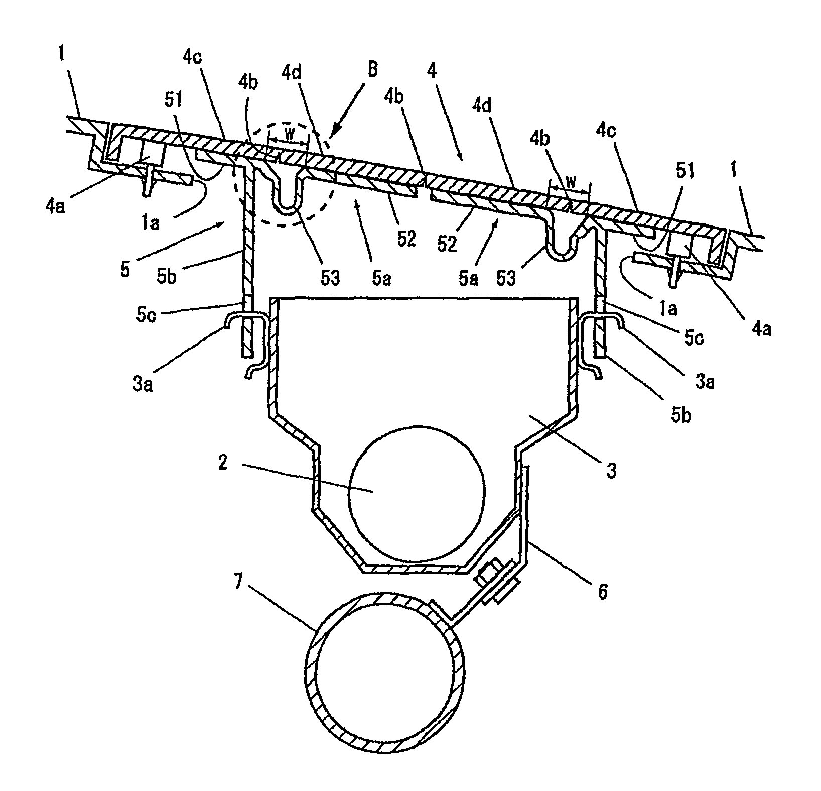
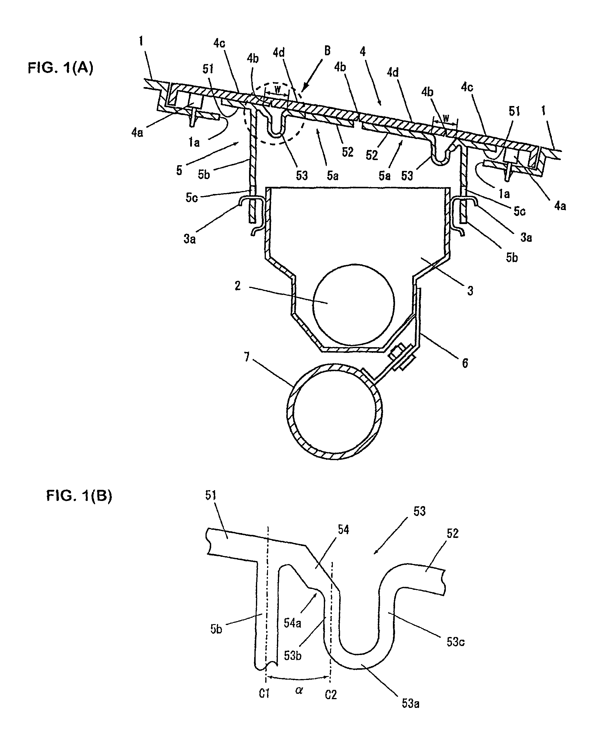
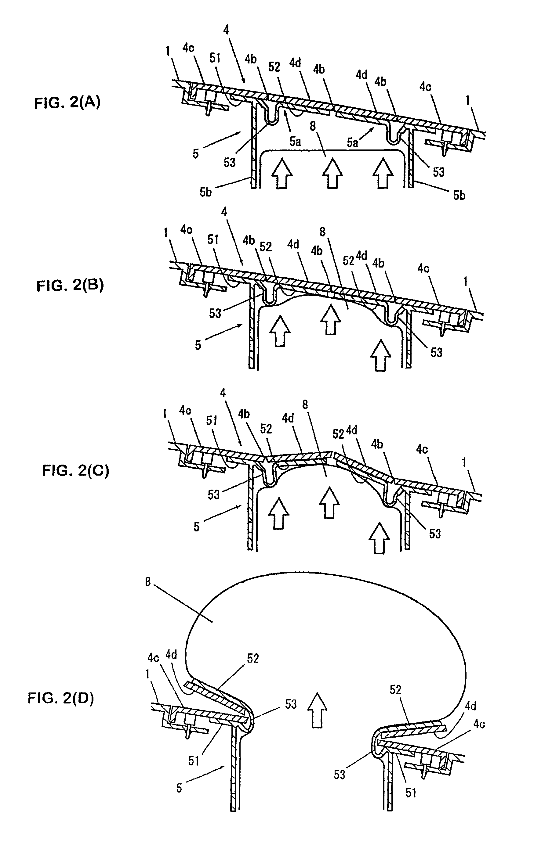
[0015]According to the above-described airbag-releasing structure, inner case, and airbag device of the present invention, by forming the straight section in the hinge portion, the rigidity thereof in the direction in which the airbag is released can be increased. Accordingly, if the hinge portion is pushed during inflation and deployment of the airbag, deformation in the direction in which the airbag is released can be reduced, whereby the airbag can be smoothly released in the vehicle. Further, by forming the straight section in the hinge portion, the width of the hinge portion can be reduced. This reduces the width of a non-welded portion left between the outer panel and the inner panel, and increases the effect of the inner panel as a reinforcement member for the outer panel. Further, by forming the straight section in the hinge portion, the length of the hinge portion can be increased, without increasing the width of the hinge portion. This effectively provides the necessary range of movement for the hinge portion to open the outer panel, and secures the flexibility of the hinge portion.
[0016]Further, by forming the straight section between the supporting portion or the flap portion and the apex section of the hinge portion, beneficial effects of the present invention can be easily exerted while preserving the shape of conventional hinge portions. Further, the slanted section formed between the straight section and the supporting portion helps the hinge portion turn, while reducing the width of the hinge portion. Further, by making the straight section thin, the flexibility necessary for the hinge portion to turn is secured, while the rigidity of portions required to be rigid is maintained. Further, in the case where the hinge portion is provided in a pair so that the hinge portions face each other, the present invention may be applied to either one. The effects of the present invention can be exerted as long as the present invention is applied to one of or each of them.

Problems solved by technology

However, since the hinge portion disclosed in Japanese Unexamined Patent Application Publication No. 2006-96267 is generally thicker on the fixing portion side, the amount by which it stretches when an outer panel opens outward is small.
If the diameter of the U-shaped portion is increased, however, the width w of the non-welded portion (refer to FIG. 5) left between the outer panel and each inner panel increases, resulting in a problem in that the effect of the inner panels as reinforcements for the outer panel is reduced.
In addition, if the size of the hinge portion is increased, the entire hinge portion is pushed during inflation and deployment of the airbag, resulting in another problem in that the door portions of the outer panel cannot smoothly open outward.
The hinge structure disclosed in PCT Japanese Translation Patent Publication No. 2003-137057 has a problem in that, since the portion which is most likely to be stretched when the door portions of the outer panel open outward (the apex section of the curved portion) is thin, the stress is concentrated too much on the apex section of the curved portion.

Method used


Image

  • Airbag-releasing structure, inner case, and airbag device
  • Airbag-releasing structure, inner case, and airbag device
  • Airbag-releasing structure, inner case, and airbag device

Examples


fourth embodiment

[0037]The fourth embodiment shown in FIG. 3(C) shows the case where the supporting portion 51 and the side wall 5b form an angle of substantially 90° with each other. In this case, because the airbag is released along the side wall 5b, the straight sections in the connecting section 53b adjacent to the supporting portion and in the connecting section 53c adjacent to the flap portion also form an angle of substantially 90° with the supporting portion 51.

fifth embodiment

[0038]The fifth embodiment shown in FIG. 3(D) shows the case where the thickness of the apex section 53a is larger than the thickness of the connecting section 53b adjacent to the supporting portion and the connecting section 53c adjacent to the flap portion. In this case, the rigidity of the apex section 53a, which tends to be stretched when the hinge portion 53 turns, can be increased. This naturally makes the connecting section 53b adjacent to the supporting portion and the connecting section 53c adjacent to the flap portion constitute thinned portions, helping the hinge portion 53 turn by creating a low-rigidity portion usable as the base point of the turn.

[0039]The sixth embodiment shown in FIG. 3(E) shows the case where no slanted section 54 is formed. In this case, a connecting section 55 between the supporting portion 51 and the connecting section 53b adjacent to the supporting portion is formed so as to smoothly connect them to each other. The connecting section 55 may be t...


PUM


Abstract

An airbag-releasing structure capable of smoothly releasing an airbag in the vehicle, an inner case, and an airbag device are provided. In one form, the inner case of the present invention includes the inner panels connected to the inside of the outer panel, and the side walls defining the space for housing the retainer. Each inner panel includes the supporting portion connected to the fixing portion of the outer panel, the flap portion welded to the door portion, and the hinge portion formed between the supporting portion and the flap portion. The hinge portion has the apex section, the connecting section adjacent to the supporting portion, which connects the supporting portion and the apex section, and the connecting section adjacent to the flap portion, which connects the flap portion and the apex section. The connecting section adjacent to the supporting portion and the connecting section adjacent to the flap portion each have a straight section extending in the direction in which the airbag is released.

Description

FIELD OF THE INVENTION[0001]The present invention relates to an airbag-releasing structure, an inner case, and an airbag device for an airbag installed in a vehicle such as a car. More specifically, the present invention relates to an airbag-releasing structure capable of smoothly releasing an airbag in the vehicle when an airbag device is activated, an inner case, and an airbag device.BACKGROUND OF THE INVENTION[0002]Typically, vehicles, such as cars, are equipped with airbag devices that restrain occupants by inflating and deploying airbags in the vehicles in case of a crash. Various types of airbag devices, such as driver airbag devices equipped in steering wheels, passenger airbag devices equipped in instrument panels, side airbag devices equipped in side panels or seats of vehicles, and curtain airbag devices equipped in areas above doors, have been developed and used. These airbag devices are normally stored in vehicle components so as to make their presence unnoticeable. In a...

Claims


Application Information

Patent Timeline
Patent Type & Authority Patents(United States)
IPC IPC(8): B60R21/20B60R21/215
CPCB60R21/205B60R21/2165B60R2021/21537
Inventor KANNO, YUKI
Owner JOYSON SAFETY SYST JAPAN KK
Why Eureka
Try Eureka