Sustainably constructed heat dissipating integrated lighting surface

a technology of integrated lighting and heat dissipation panel, which is applied in the direction of lighting support devices, furniture parts, synthetic resin layered products, etc., can solve the problems of easy failure of external wiring, reduce the burden on limited natural resources, reduce the carbon footprint of products, and reduce the effect of voc emissions

Active Publication Date: 2010-06-29
LIGHTING SCI GROUP
View PDF14 Cites 22 Cited by
  • Summary
  • Abstract
  • Description
  • Claims
  • Application Information

AI Technical Summary

Benefits of technology

[0018]The present invention solves the afore-mentioned problems in the art by providing a lighted heat dissipating panel comprising a heat dissipating panel in combination with an embedded light source, or a plurality of embedded light sources, in such a manner that heat is conducted away from the light source or sources (in the case of LED light sources the heat is conducted away from the semiconductor junction) and transferred to at least one radiating surface of the panel and may also be conducted through the mounting points of the panel to an external structure. As used herein, “heat dissipating” means that heat energy is conducted away from the heat source and either radiated or conducted into surrounding structure, or both. In accordance with a preferred embodiment of the invention, a core fabricated from expanded or honeycombed recycled aluminum is combined with glass-carbon composite materials to provide a heat dissipating panel allowing heat to be conducted away from the light source or sources; furthermore, this preferred embodiment is fabricated using urethane materials, for example soy-based urethane or functional equivalents as described herein. The use of recycled aluminum allows re-use and recycling of materials, resulting in reduced burden on limited natural resources. The use of soy-based urethane eases the carbon footprint of the product by generating no, or very little, VOC emissions, and enables the invention to be of thinner cross section for a given thickness as compared to other ester-based resins. While it is preferable that soy-based urethane be used it is not strictly necessary; ester resins and other urethane products may be used in the construction of the apparatus.
[0019]Recent advances in the availability of certain materials such as carbon or graphite fiber, and in the availability of re-used materials such as recycled aluminum, now make it feasible to construct heat dissipating panels that are lightweight, constructed from sustainable recycled materials, and are of sufficient stiffness to be used as structural components in architectural and shelving applications. The use of recycled materials eases the burden of new construction on precious and expensive natural resources such as aluminum. A panel may be constructed of the afore-mentioned materials, for example, by filling an aluminum honeycomb core with fiberglass, carbon or graphite fiber and bonding such fiberglass, carbon or graphite fiber with carbon material or with a resin such as, for example, ester resins, urethane, and soy-based urethane. Such a structure is lightweight, thermally conductive, machinable, moldable to any desired shape, and stiff.
[0021]A preferred embodiment of the present invention provides electrical connectivity for the power connection of the lighting elements through shelf mounting points by use of ball detent assemblies which are in electrical communication with a power supply and with said lighting elements, thereby eliminating the need for external wiring. Such external wiring is prone to failure, requires the use of external connectors, and is unsightly and thus undesirable in architectural applications.

Problems solved by technology

Such external wiring is prone to failure, requires the use of external connectors, and is unsightly and thus undesirable in architectural applications.

Method used


Image

  • Sustainably constructed heat dissipating integrated lighting surface
  • Sustainably constructed heat dissipating integrated lighting surface
  • Sustainably constructed heat dissipating integrated lighting surface

Examples


Embodiment Construction

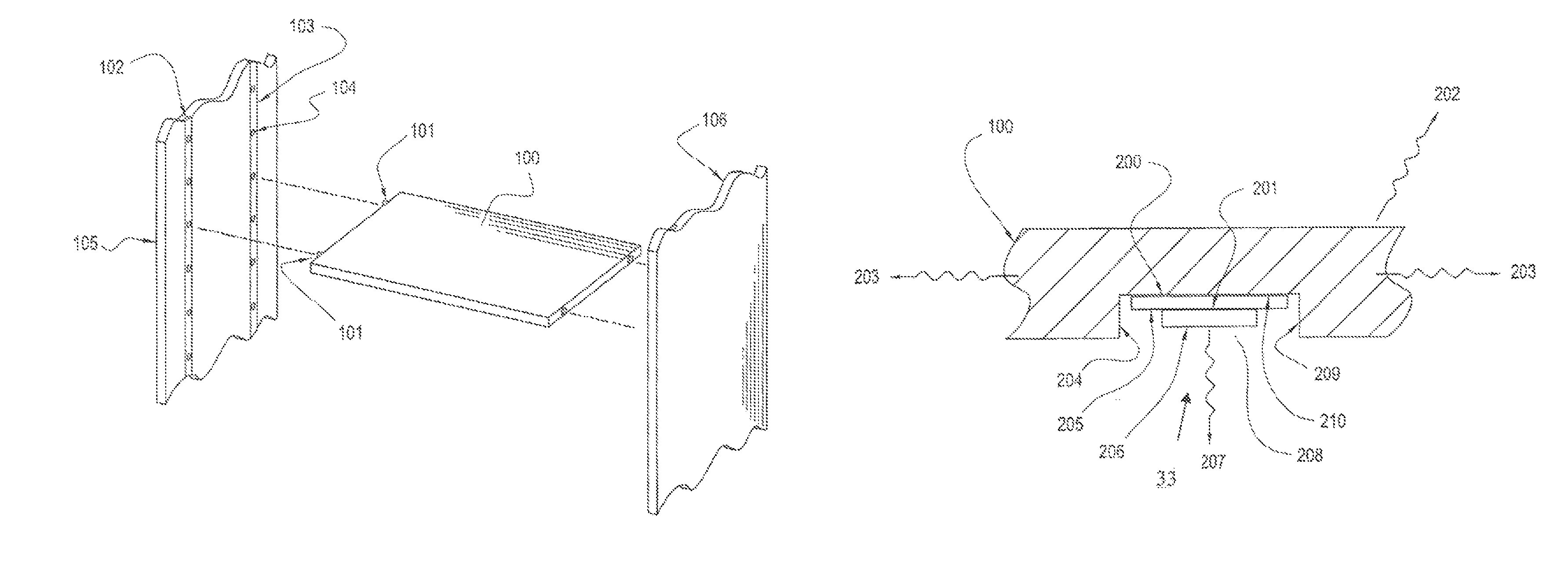
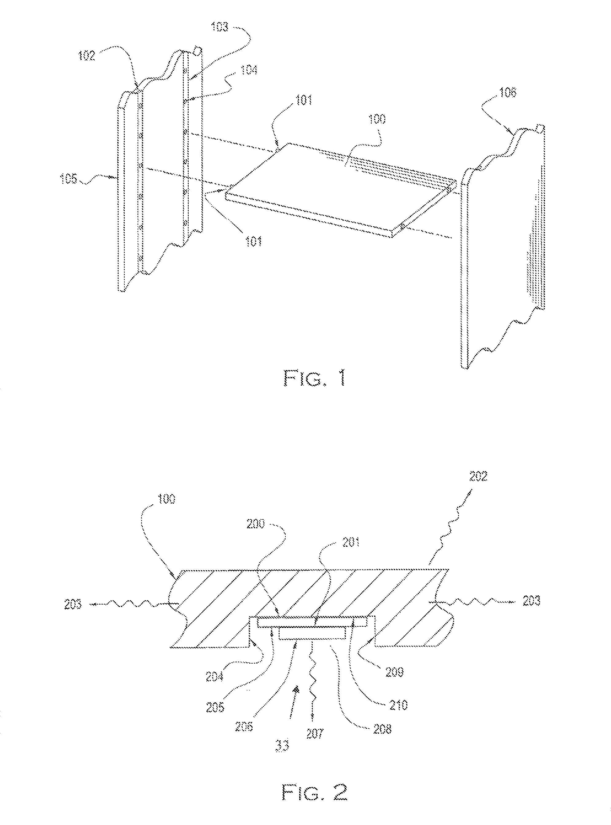
[0031]Although the following detailed description contains many specifics for the purposes of illustration, anyone of ordinary skill in the art will appreciate that many variations and alterations to the following details are within the scope of the invention. Accordingly, the following preferred embodiments of the invention are set forth without any loss of generality to, and without imposing limitations upon, the claimed invention. First, the construction details of the heat dissipating panel itself are described, followed by a detailed description of the lighted heat dissipating panel apparatus.

a. Heat Dissipating Panel

[0032]The heat dissipating panel may be comprised of a structural core in combination with a filler material. The structural core may take a variety of shapes and may be fabricated from a number of different materials as described below and functional equivalents thereof. The filler may be a number of materials as described below, such as glass-carbon material, and...


PUM

PropertyMeasurementUnit
temperatureaaaaaaaaaa
temperaturesaaaaaaaaaa
transparentaaaaaaaaaa

Abstract

A lighted heat dissipating panel made of sustainable renewable materials such as recycled aluminum and soy-based urethane, for use in architectural or shelving applications. The panel may be flat, rectangular, curvilinear, or of varying cross section so as to include any three-dimensional shape as desired. Lightweight materials such as carbon fiber, fiberglass, resin, soy-based urethane, and similar materials are used in combination with thermally conductive structural materials, such as expanded aluminum honeycomb, preferably fabricated from recycled aluminum, to provide a stiff, lightweight, machinable, moldable, and thermally conductive panel for use with lighting elements. Lighting elements are housed within the panel, providing illumination as desired. Heat is transferred from the lighting elements through the panel to the supporting structure and radiated from the panel itself, providing cooling effect for the lighting elements, reducing the temperature in the immediate vicinity of the lighting elements and providing for longer lighting element life.

Description

CROSS REFERENCE TO RELATED APPLICATIONS[0001]Not applicable.STATEMENT REGARDING FEDERALLY SPONSORED RESEARCH OR DEVELOPMENT[0002]Not applicable.INCORPORATION-BY-REFERENCE OF MATERIAL SUBMITTED ON A COMPACT DISK[0003]Not applicable.BACKGROUND OF THE INVENTION[0004]1. Field of the Invention[0005]The present invention generally relates to a lighted heat dissipating panel comprised of embedded light sources providing illumination as desired by a uses; more specifically, the present invention relates in at least one embodiment in which the heat dissipating panel is comprised of sustainable materials such as recycled expanded aluminum embedded in glass-carbon composite and in which the light emitting element is a Light Emitting Diode (LED), or a plurality of LEDs, which are in thermal contact with the light emitting surface whereby heat is transferred from the LEDs to the heat dissipating surface. The LEDs are thus cooled and are able to operate at a higher lumen output and with greater r...

Claims


Application Information

Patent Timeline
Patent Type & Authority Patents(United States)
IPC IPC(8): F21V29/00
CPCA47B96/021F21V29/89A47F11/00B32B3/12B32B3/30B32B5/26B32B7/12B32B9/00B32B15/14B32B15/20B32B17/04B32B27/04B32B27/36B32B27/40E04C2/26E04C2/365F21S48/328F21V29/004F21V33/0012F21V33/006F21V29/87F21W2131/301F21Y2101/02A47B2200/0019B32B5/024B32B9/005B32B27/20B32B27/281B32B27/38B32B29/002B32B2262/101B32B2262/106B32B2307/302B32B2307/40B32B2307/412B32B2457/00F21Y2115/10F21S45/47
Inventor MAXIK, FREDRIC S.
Owner LIGHTING SCI GROUP
Why Eureka
Try Eureka