TSA process

a technology of tsa process and raw gas, which is applied in the direction of separation process, dispersed particle separation, chemistry apparatus and process, etc., can solve the problems of unavoidable changes or fluctuations in the design load value of raw gas supplied to the tsa process

Inactive Publication Date: 2010-06-29
LINDE AG
View PDF1 Cites 56 Cited by
  • Summary
  • Abstract
  • Description
  • Claims
  • Application Information

AI Technical Summary

Benefits of technology

[0006]An aspect of the invention is to provide a method of for separating an at least two-component raw gas by means of a TSA process, which makes it possible to compensate for these changes or fluctuations in the design load value of the raw gas.

Problems solved by technology

In many TSA processes—particularly in TSA processes which are integrated into multistage processes, such as for example cryogenic CO or C2H4 production—unavoidable changes or fluctuations are often encountered in the design load value of the raw gas supplied to the TSA process.

Method used


Image

  • TSA process
  • TSA process
  • TSA process

Examples


Embodiment Construction

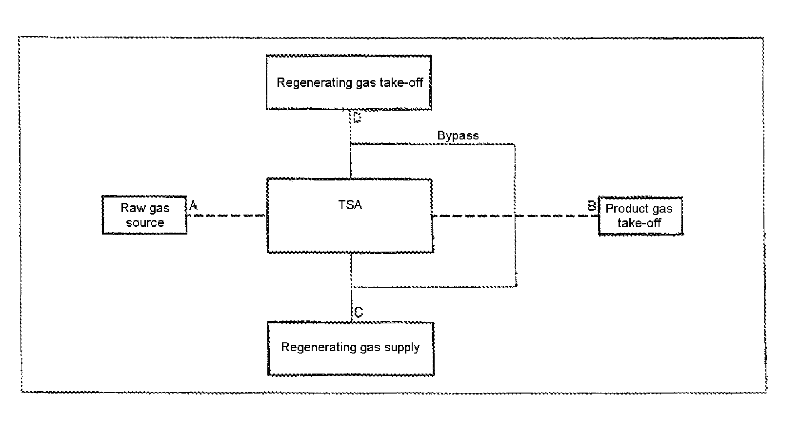
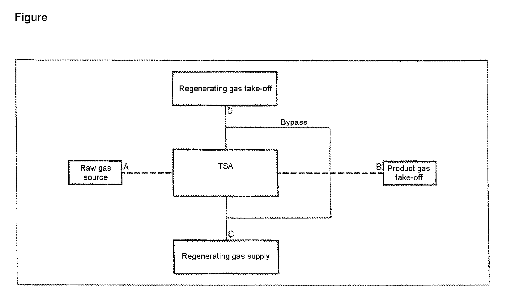
[0011]To explain the methodology according to the invention, reference will be made to the FIGURE—which has already been presented in German patent application 10 2005 032 025 cited above.

[0012]In a schematized form, this shows a TSA method, or the incorporation of a TSA method into an arbitrary process, as has been explained above.

[0013]The term “raw gas source” is intended to mean any source of the raw gas to be supplied to the TSA process. The term “product gas take-off” is also intended to cover any further method steps in which the product gas obtained by the TSA process is subjected to an arbitrary further treatment.

[0014]The term “regenerating gas supply” used in the FIGURE is intended to mean any source of the regenerating gas. In this context, some of the product and / or raw gas may be used as a regenerating gas; it may nevertheless also come from an independent (“external”) gas source.

[0015]The term “regenerating gas take-off” is intended to cover any recipients of the gas ...


PUM


Abstract

In a TSA process of an at least two-component raw gas, to adjust for fluctuation in load, the cycle time of at least one method step is extended in the event of falling below the design load value.

Description

[0001]The invention relates to a method for separating an at least two-component raw gas by means of a Temperature Swing Adsorption (TSA) process, which comprises at least the method steps of adsorption and regeneration, the cycle times of the individual method steps being configured for a design load value of the raw gas.[0002]Adsorption processes or methods, in which the laden adsorbent is regenerated by increasing the temperature—optionally together with further measures which support regeneration of the laden adsorbent—are referred to as T(emperature)S(wing)A(dsorption) methods. In a TSA method, at least two adsorbent beds are exposed to a feed gas mixture of two or more components whereby one or more of the components of the feed gas mixture is preferably adsorbed by the adsorbent. The flow of feed gas to one of the adsorbers is then interrupted and a regeneration gas is introduced to the adsorbent bed to recover the adsorbed component(s). During the regeneration step, the adso...

Claims


Application Information

Patent Timeline
Patent Type & Authority Patents(United States)
IPC IPC(8): B01D53/02
CPCB01D53/0462B01D2259/416B01D2259/40007B01D53/00B01D53/02
Inventor LEITMAYR, WERNERMULLER, RALF
Owner LINDE AG
Why Eureka
Try Eureka