Disk drive detecting defective spiral servo track

a spiral servo track and disk drive technology, applied in the field of disk drives, can solve the problems of high cost of external servo writers, affecting the production process of disk drives, and requiring a clean room environment,

Inactive Publication Date: 2010-06-29
WESTERN DIGITAL TECH INC
View PDF36 Cites 113 Cited by
  • Summary
  • Abstract
  • Description
  • Claims
  • Application Information

AI Technical Summary

Problems solved by technology

However, external servo writers are expensive and require a clean room environment so that a head positioning pin can be inserted into the head disk a

Method used


Image

  • Disk drive detecting defective spiral servo track
  • Disk drive detecting defective spiral servo track
  • Disk drive detecting defective spiral servo track

Examples


Embodiment Construction

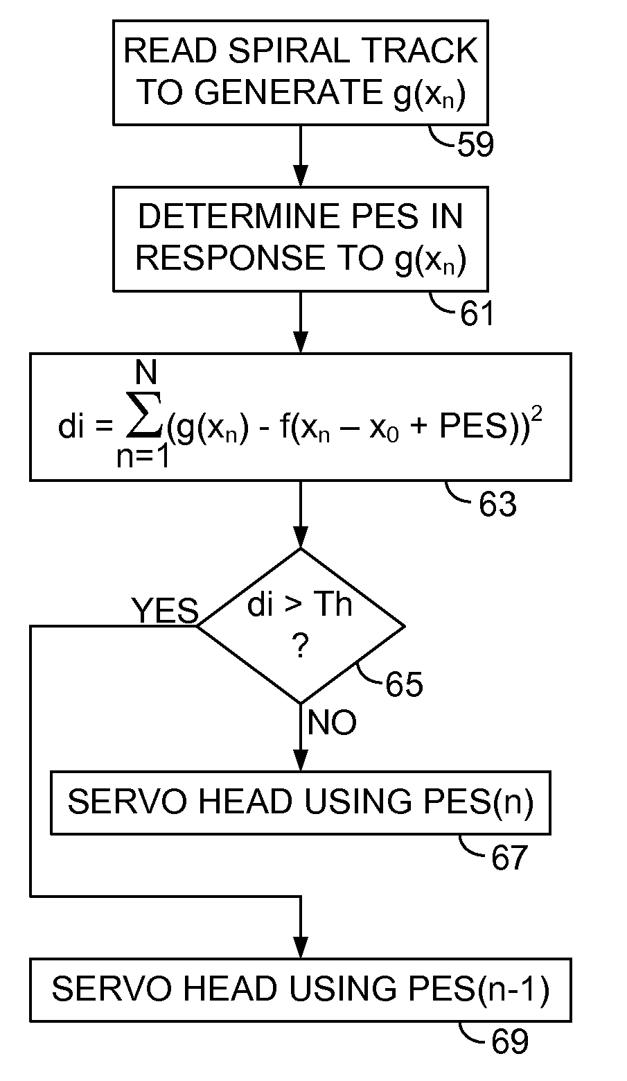
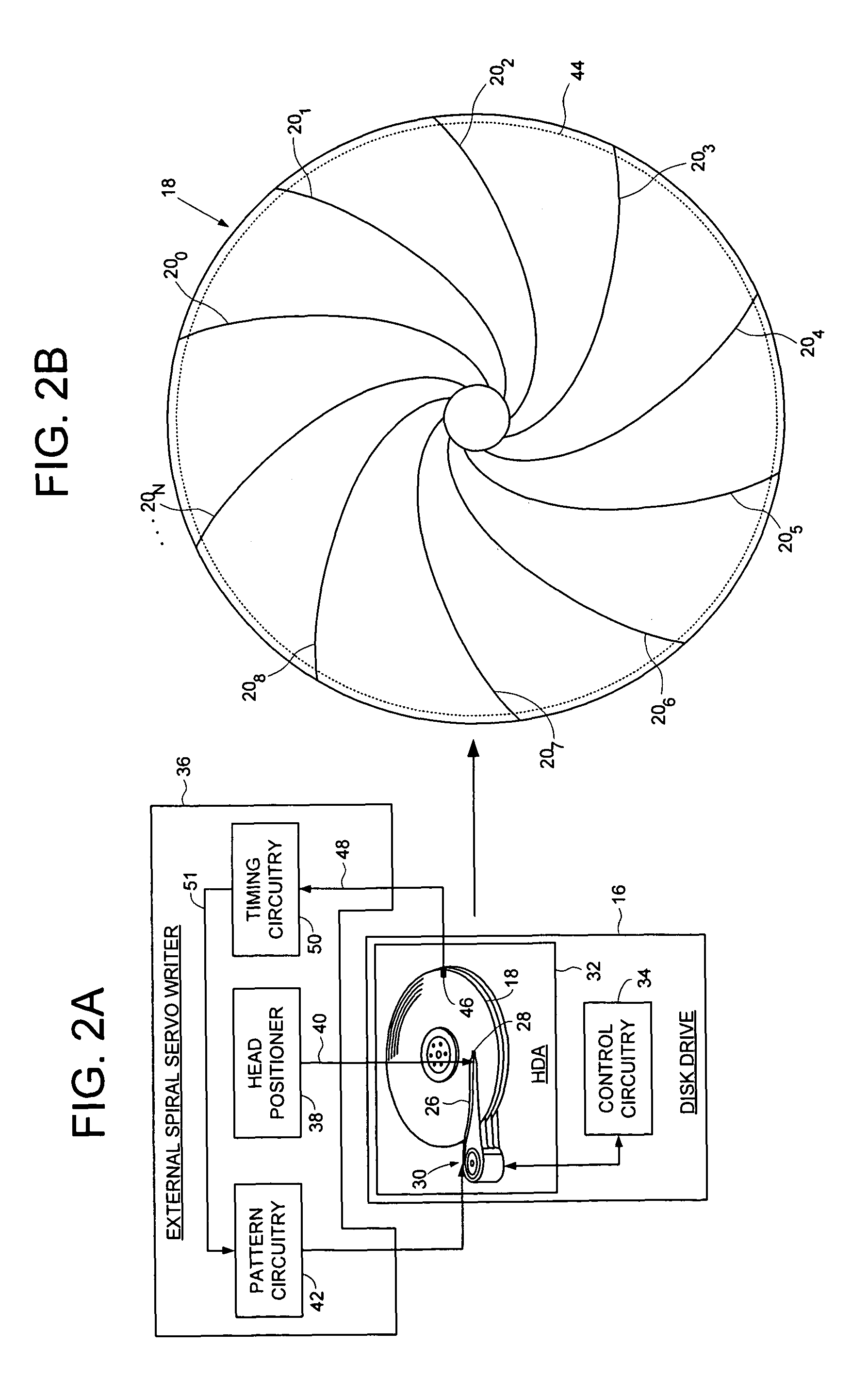
[0023]FIGS. 2A and 2B show a disk drive 16 according to an embodiment of the present invention comprising a disk 18 including a plurality of spiral tracks 200-20N, wherein each spiral track comprises a high frequency signal 22 interrupted by a sync mark 24 at a sync mark interval (FIG. 4B), and a head 28 actuated over the disk 18. FIG. 8A illustrates how a spiral tracks 20, is read to generate a spiral track crossing signal g(xn), where xn is a time in a demodulation window. A position error signal (PES) is determined in response to g(xn) is determined (e.g., by integrating the spiral track crossing signal as shown in FIG. 6), and a deviation index is computed by correlating g(xn) with a nominal track crossing signal shifted by the PES. When the deviation index is less than a threshold, the PES is used to servo the head 28 over the disk 18. In one embodiment, the deviation index is computed according to:

[0024]d⁢⁢i=∑n=1N⁢(g⁡(xn)-f⁡(xn-x0+PES))2

where di is the deviation index and f(xn...


PUM


Abstract

A disk drive is disclosed comprising a disk and a head actuated over the disk, wherein the disk comprises a plurality of spiral tracks, each comprising a high frequency signal interrupted by a sync mark at a sync mark interval. The head is used to read a spiral track to generate a spiral track crossing signal g(xn), where xn is a time in a demodulation window. A position error signal (PES) is determined in response to g(xn), and a deviation index is computed by correlating g(xn) with a nominal track crossing signal shifted by the PES. When the deviation index is less than a threshold, the PES is used to servo the head over the disk.

Description

BACKGROUNDDescription of the Related Art[0001]When manufacturing a disk drive, servo sectors 20-2N are written to a disk 4 which define a plurality of radially-spaced, concentric data tracks 6 as shown in the prior art disk format of FIG. 1. Each data track 6 is partitioned into a plurality of data sectors wherein the servo sectors 20-2N are considered “embedded” in the data sectors. Each servo sector (e.g., servo sector 24) comprises a preamble 8 for synchronizing gain control and timing recovery, a sync mark 10 for synchronizing to a data field 12 comprising coarse head positioning information such as a track number, and servo bursts 14 which provide fine head positioning information. The coarse head position information is processed to position a head over a target track during a seek operation, and the servo bursts 14 are processed to maintain the head over a centerline of the target track while writing or reading data during a tracking operation.[0002]In the past, external serv...

Claims


Application Information

Patent Timeline
IPC IPC(8): G11B21/02G11B5/09G11B5/596
CPCG11B5/596G11B5/59633G11B5/59666G11B20/10046G11B20/10425G11B20/1816G11B20/10222G11B20/10009G11B2220/2516G11B20/1403G11B2020/1281G11B2020/1287
Inventor LIANG, JIANGANGWEERASOORIYA, SIRI S.
Owner WESTERN DIGITAL TECH INC
Why Eureka
Try Eureka