Bidirectional battery power inverter

a technology of bidirectional battery and inverter, which is applied in the direction of electric variable regulation, process and machine control, instruments, etc., can solve the problems of quite high conductance loss at such small dc voltage, and achieve the effect of reducing the effective current load, reducing the cost, and facilitating manufacturing

Active Publication Date: 2010-06-29
SMA SOLAR TECH AG
View PDF14 Cites 26 Cited by
  • Summary
  • Abstract
  • Description
  • Claims
  • Application Information

AI Technical Summary

Benefits of technology

[0013]The present invention combines the advantages of low conduction losses and the possibility of utilizing a planar transformer without the trade-off of an unfavorable high apparent power of the transformer and switch overvoltages on the primary side, a restricted operating range and high conduction and switch losses on the low voltage side. Put another way, this means that with the topology of the invention, as contrasted to prior art, a very low-loss, fully resonant switching is made possible on the high current side by the fact that the adjustment stage (boost-buck chopper) is activated in operation ranges in which the voltage needs to be adapted.
[0014]In accordance with the invention, there is provided that a DC-AC converter circuit element is provided, said converter circuit element lying on the output side of the inverter and comprising a boost-buck chopper that is connected between the DC-DC converter and the DC-AC converter circuit element. As a result, switching losses due to non-optimal operation in which the DC-DC converter cannot be switched resonantly and an unfavorable current / voltage configuration in the optimal point of operation are avoided.
[0015]By virtue of the fact that a resonant switching element is distributed in circuit parts with staggered clocking, the capacitor load is low and the HF ripple current in the DC source is low as well.
[0017]If the clock rate of the half-bridge circuit is less than the resonant frequency obtained from the leakage inductance of the transformer and the series resonant capacitance, switching on should always occur at zero current since in this case the switching losses are low or inexistent. In accordance with another advantageous developed implementation of the invention, there is provided a synchronous actuation of the boost-buck chopper and of the resonant converter. The synchronous actuation has the advantage that the effective current load is minimized in the capacitors of the power inverter.
[0018]A particular effect of benefit is achieved if the transformer is configured to be a planar transformer, said planar transformer being provided with two printed circuit boards. Both the core of the transformer and the printed circuit boards are housed in a housing. A cast housing is manufacturable at lower cost since projections needed in the cast housing of a planar transformer are easier to manufacture. A planar transformer with two printed circuit boards is moreover manufacturable at a lower cost than a planar transformer having a large printed circuit board. A large printed circuit board is more expensive than two small ones.

Problems solved by technology

The problem arising here is that the conduction losses are quite high at such small DC voltages.

Method used


Image

  • Bidirectional battery power inverter
  • Bidirectional battery power inverter
  • Bidirectional battery power inverter

Examples


Embodiment Construction

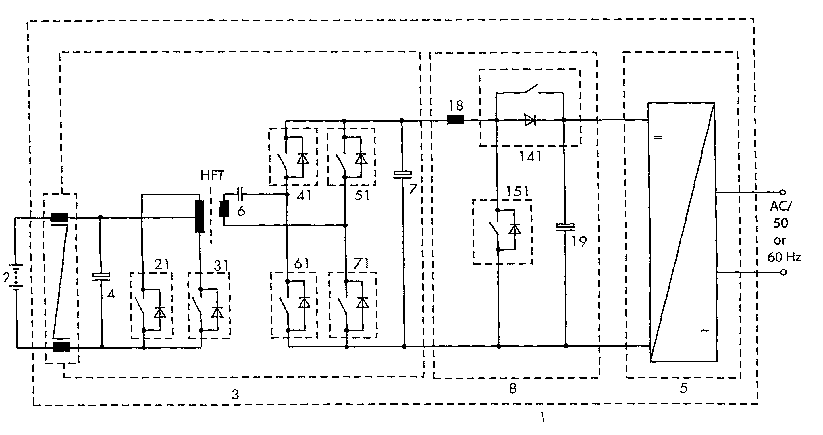
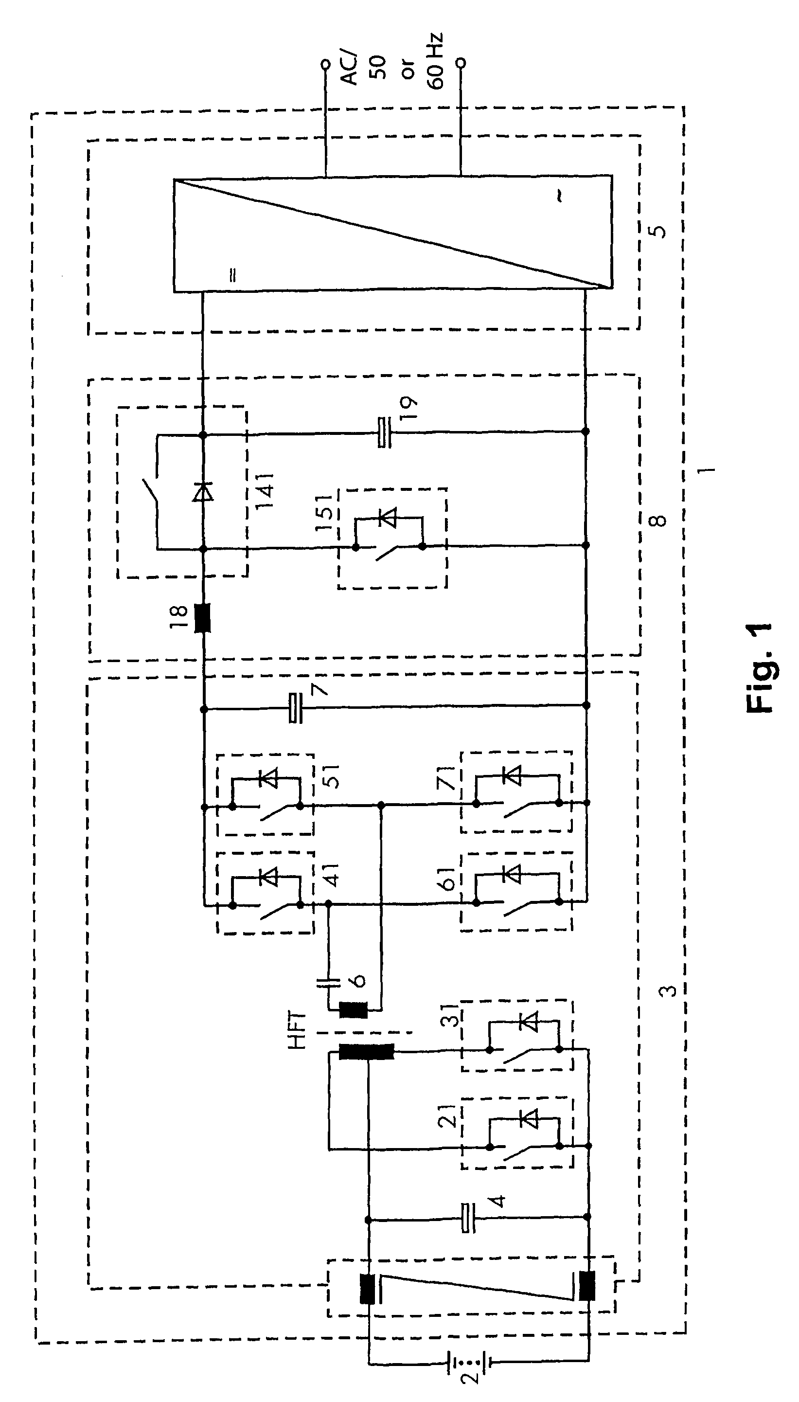
[0029]FIG. 1 shows a power inverter 1 of the invention, for example for supplying AC consumers in island networks. Said power inverter is connected to a battery 2. The power inverter 1 includes one DC-DC converter circuit element 3 with a capacitor 4 connected in parallel to the battery 2 and one HF transformer HFT.

[0030]The power inverter 1 further includes a DC-AC converter circuit element 5 that lies on the output side of the power inverter 1 and a boost-buck chopper 8 that is connected between the DC-DC converter circuit element 3 and the DC-AC converter circuit element 5. The DC-AC converter circuit element 5 is configured to be monophase.

[0031]The inverter 1 is configured to be a bidirectional battery power inverter and serves for generating an AC output voltage from the battery voltage in a discharge mode of operation and for charging the battery 2 in the charge mode. Together with a resonant capacitor 6, the HF transformer HFT forms a resonant circuit.

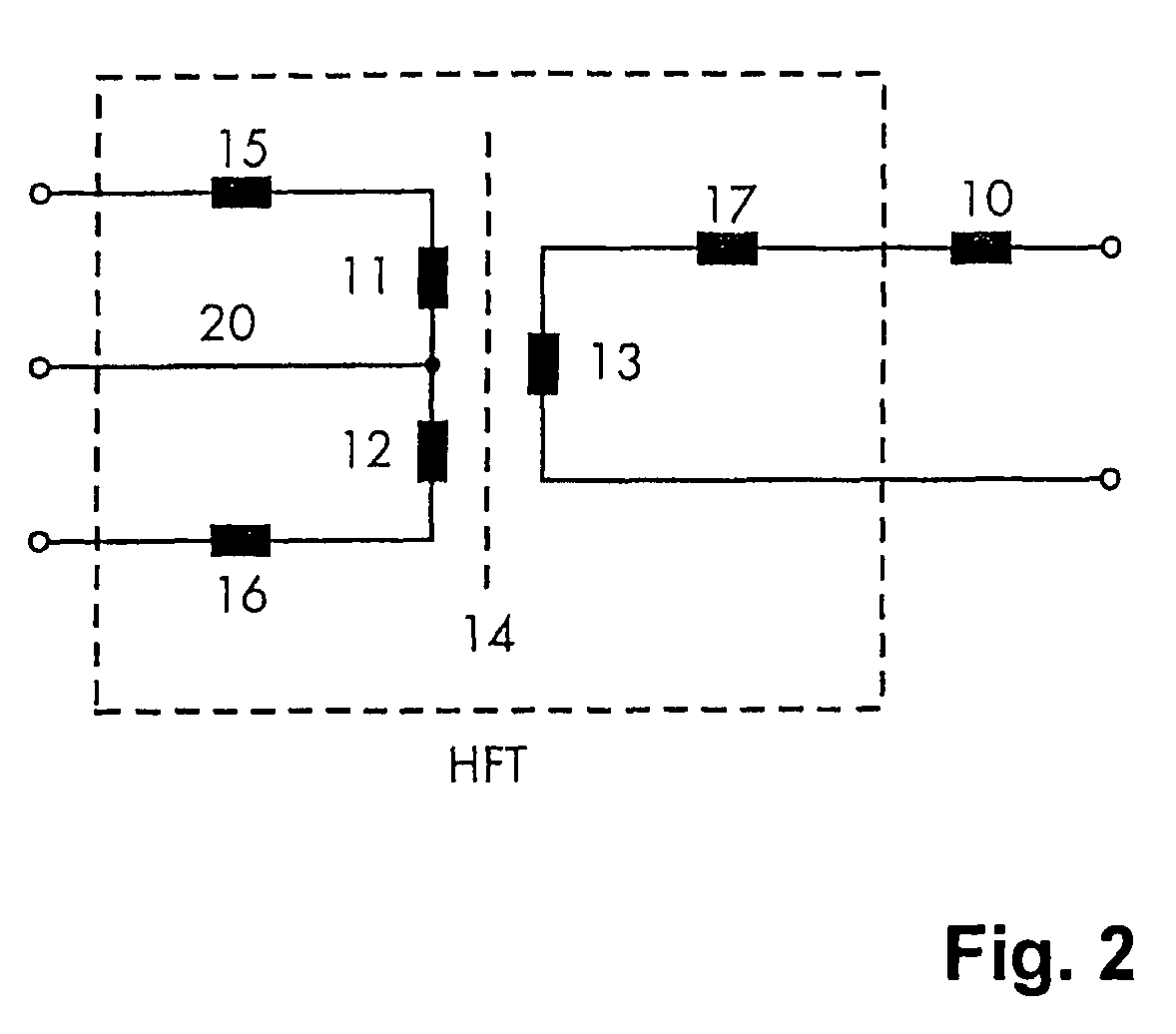
[0032]FIG. 2 shows an e...


PUM


Abstract

Disclosed is a bi-directional battery power inverter (1) comprising a DC-DC converter circuit element (3) to which the battery (2) can be connected in order to generate an AC output voltage from a battery (2) voltage in a discharging mode while charging the battery (2) in a charging mode. The inverter (1) further comprises an HF transformer which forms a resonant circuit along with a resonant capacitor (6). In order to increase the efficiency of said battery power inverter, the transformer is provided with two windings (11, 12) with a center tap (20) on the primary side, said center tap (20) being connected to a power electronic center-tap connection with semiconductor switches (21, 31) while a winding (13) to which the resonant capacitor (6) is serially connected provided on the secondary side.

Description

[0001]This application claims Priority from German Application No. DE 10 2005 023 290.6 filed on 20 May 2005BACKGROUND OF THE INVENTION[0002]1. Field of the Invention[0003]The present invention relates to a bidirectional battery power inverter as set forth in the preamble of claim 1 and claim 2.[0004]2. Description of the Prior Art[0005]Bidirectional power inverters serve on the one side to convert a DC battery voltage from 12 volt into a 50 Hz or 60 Hz AC voltage of e.g., 230 volt, on the other side however also to charge the battery from the AC voltage. The energy flows both from the battery to a DC-AC converter and from the DC-AC converter to the battery. The problem arising here is that the conduction losses are quite high at such small DC voltages.[0006]A power inverter with a half-bridge array on the primary side and a full bridge array on the secondary side is known from the document EP 0 820 893 A2.[0007]A bidirectional DC-DC converter is known from EP 1 458 084 A2. It inclu...

Claims


Application Information

Patent Timeline
Patent Type & Authority Patents(United States)
IPC IPC(8): H02M3/335H02M7/5387
CPCH02M3/3372H02M2001/007Y02B70/1491H02M2001/0058Y02B70/1433Y02B70/10H02M1/0058H02M1/007H02M7/537
Inventor FALK, ANDREAS
Owner SMA SOLAR TECH AG
Why Eureka
Try Eureka