
Method for the rotation compensation of spherical images

a technology of rotation compensation and spherical images, applied in the field of computer-aided stabilization of images, can solve the problems of limited compensation effect, image distortion, no longer being able to perform any compensation, etc., and achieve the effect of simplifying reconstruction

Inactive Publication Date: 2010-06-29
UNIVERSITY OF KIEL
View PDF8 Cites 9 Cited by
  • Summary
  • Abstract
  • Description
  • Claims
  • Application Information

AI Technical Summary

Benefits of technology

"The patent describes a way to make it easier to reconstruct spherical images that are recorded sequentially by a camera placed randomly in a scene. The camera has a sensor that detects the rotation of the camera, and this information is used to calibrate the camera and compensate for any rotation during the recording of the images. This allows for easier and more accurate reconstruction of the original color and brightness values of the images."

Problems solved by technology

Existing blur compensation methods, such as electronic image stabilization in Handy Cams, can only effect a limited compensation due to the limited angular aperture of perspective cameras, and as a result of perspective transformation the image is distorted.
Upon tilting the camera by more than the angular aperture, it is no longer possible to perform any compensation.
It represents a fundamental difficulty of electronic reprocessing that a real image of a (three-dimensional) scene is only acquired by a two-dimensional pixel array.
To be able to conclude from a rotation or translation of the camera, which has taken place in the meantime solely from a sequence of images, it is necessary to numerically reconstruct the 3D scene, and even nowadays, this involves considerable effort and expenditure, particularly in real time.
However, there is always (1) a “dead zone” of the device in the immediate vicinity of the double camera and which cannot be perceived, together with (2) a “near zone” in which the parallax shift of the two cameras is noticeable.
However, for external applications, much more complex image analyses are needed to be able to obviate the use of such markings.
However, no method has been published as to how it is possible to use additional rotation data for real time rotation stabilization of the spherical image.

Method used


Image

  • Method for the rotation compensation of spherical images
  • Method for the rotation compensation of spherical images
  • Method for the rotation compensation of spherical images

Examples


Embodiment Construction

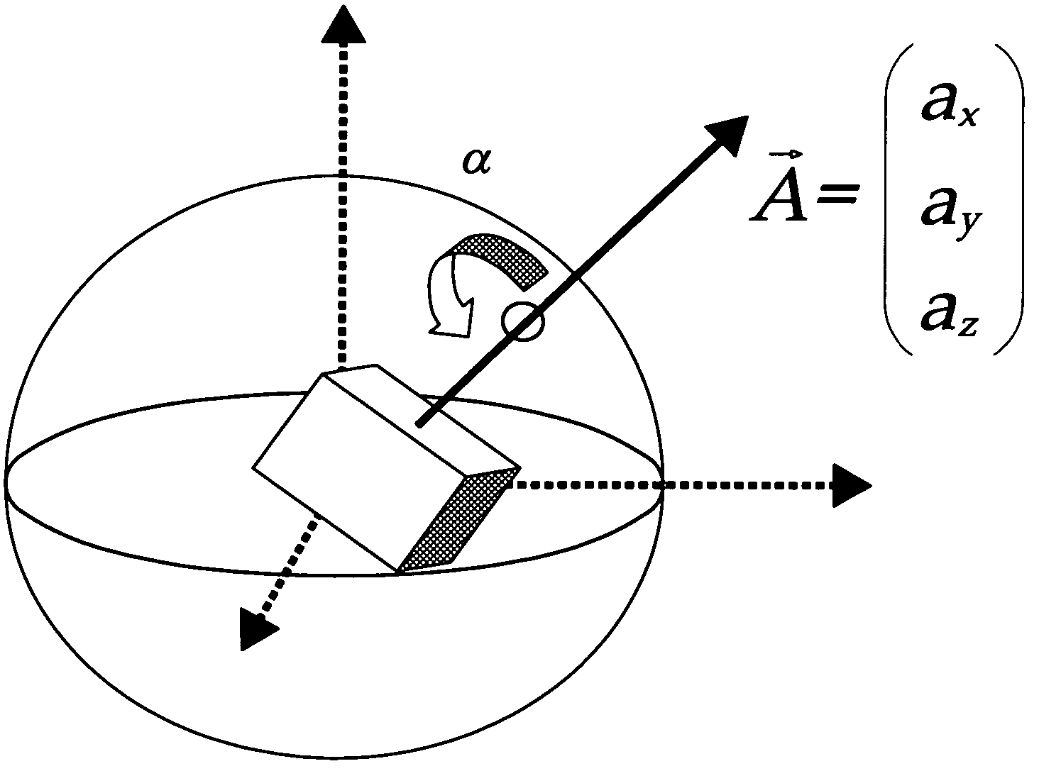
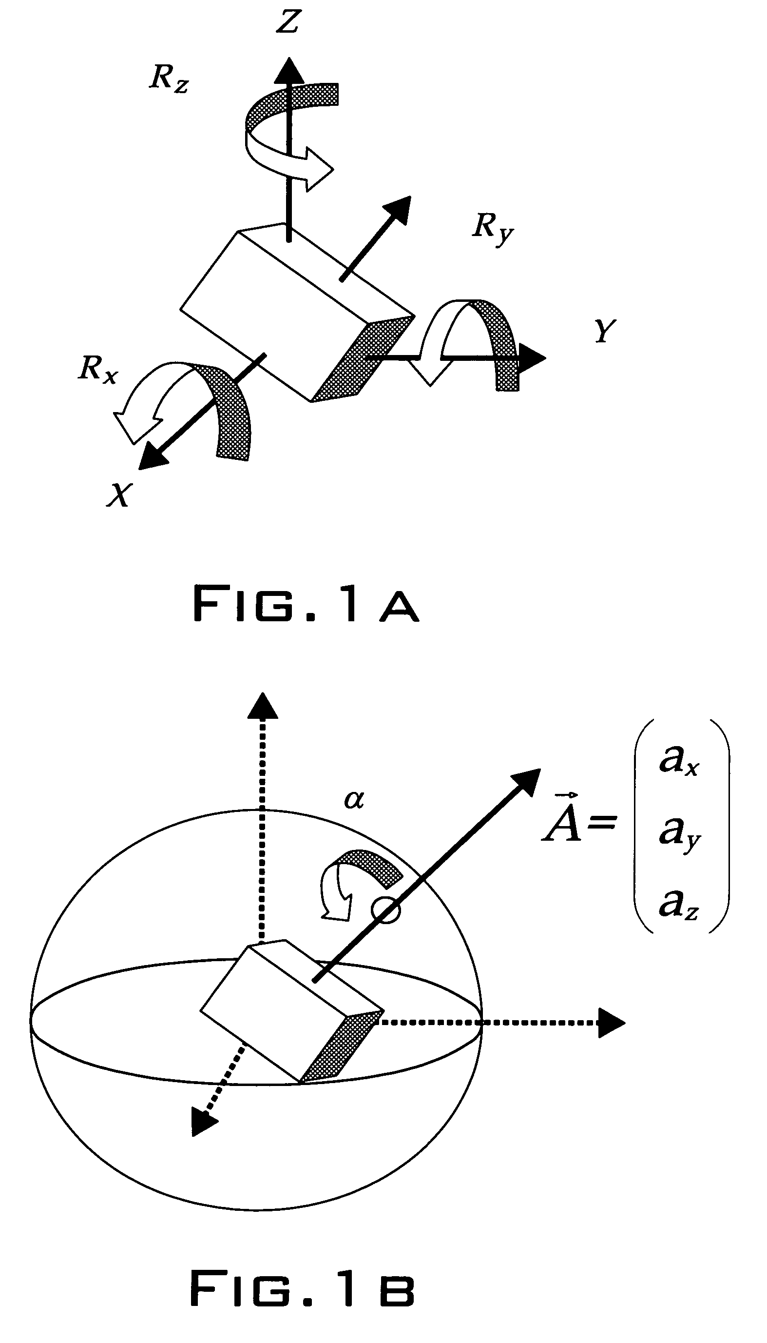
[0023]The fundamental prerequisite for performing the method according to the invention is the rigid coupling of a spherical camera with a 3DoF (Degree of Freedom) rotation sensor.

[0024]In order to simplify explanations, reference is only made hereinafter to a single fisheye camera which images a hemisphere. For all-around viewing, the method is simultaneously used for both cameras, and the inventively stabilized images are then joined together in a known manner.

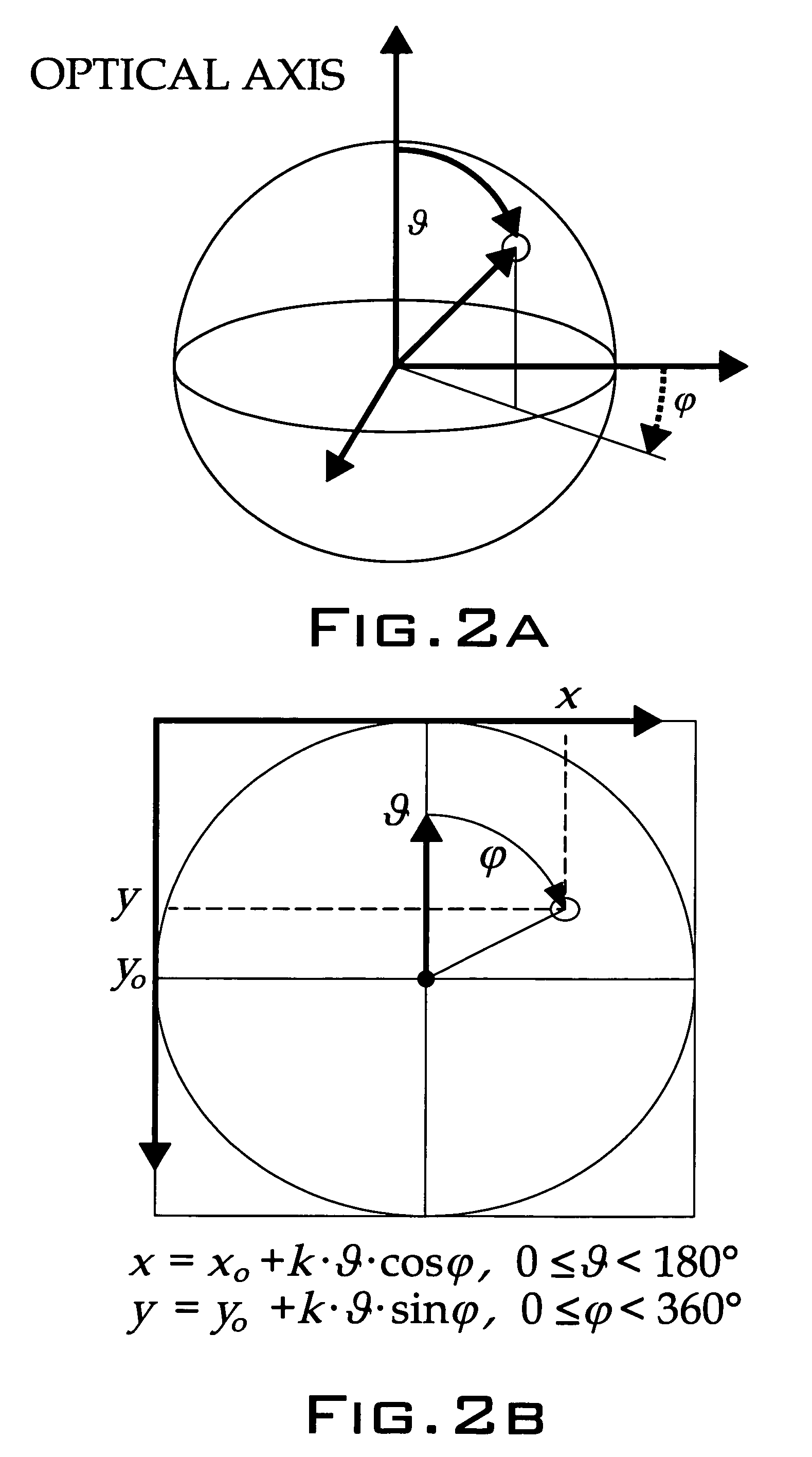
[0025]The camera pixel plane requires a two-dimensional coordinate system in 3D space. The pixel plane orientation is random. Technical CCD chips normally have square pixels in a rectangular arrangement, so the Cartesian coordinate system (x, y) is the natural choice. Its origin is typically in a corner pixel.

[0026]Through the spherical projection of the fisheye, object points are imaged on a hemisphere (of radius one) around the camera center on a circular disk in the pixel plane. The natural coordinates of the image are th...


PUM


Abstract

Method for producing a rotation-compensated image sequence allowing simplified reconstruction of the translation of a camera by real time rotation compensation of images recorded sequentially by an electronic camera randomly displaced in a scene and provided with a rotation sensor resulting from an association of color and / or brightness values of the pixels of a camera pixel field indicated by rectangular coordinates.

Description

PRIOR APPLICATIONS[0001]This application is a continuation-in-part of International Application No. PCT / DE2005 / 000613, filed on Apr. 7, 2005, which in turn bases priority on German Application No. 10 2004 017 730.9, filed on Apr. 10, 2004.BACKGROUND OF THE INVENTION[0002]1. Field of Invention[0003]The invention relates to a method for computer-assisted stabilization of images, particularly electronically recorded images (i.e., using a video camera) with respect to rotations of the camera about a random axis and by randomly large angles. The invention also relates to image recording systems using a fisheye lens for (hemi)spherical images, particularly cameras with a 3600 all-around view.[0004]2. Description of the Prior Art[0005]Electronic image stabilization methods are known and can roughly be broken down into two categories, namely (1) compensation devices for the actual camera or for the optical path from object to camera screen and (2) computer-assisted correction of the recorde...

Claims


Application Information

Patent Timeline
Patent Type & Authority Patents(United States)
IPC IPC(8): G06K9/32G06K9/36G06K9/00G09G5/00G06T15/00G06T3/00G06T3/60H04N23/40
CPCG06T3/60H04N5/23264H04N5/23248H04N5/23238H04N23/68H04N23/682H04N23/698
Inventor KOCH, REINHARD
Owner UNIVERSITY OF KIEL
Learn More