Earphone jack for eliminating power noise in mobile communication terminal, and operating method thereof

a mobile communication terminal and power noise technology, applied in the field of earphone jacks, can solve the problems of power noise generation, noise interference of inability to output clear voice signals without power noise, so as to improve call quality and eliminate power noise

Inactive Publication Date: 2010-06-29
SAMSUNG ELECTRONICS CO LTD
View PDF4 Cites 54 Cited by
  • Summary
  • Abstract
  • Description
  • Claims
  • Application Information

AI Technical Summary

Benefits of technology

[0016]It is, therefore, an object of the present invention to substantially solve the above and other problems and provide an earphone jack and an operating method thereof in which a voice signal is output in a differential signal format to eliminate power noise in a mobile communication terminal, thereby improving call quality.
[0017]It is another object of the present invention to provide an earphone jack and an operating method thereof in which, when a voice call is performed, a ground terminal becomes a ground off state, thereby eliminating power noise from the ground terminal.

Problems solved by technology

However, when the call voice signal of the call mode is output, there is a drawback in that when a voice call is performed, power noise is generated at the earphone 110 and therefore, a clear voice signal without power noise cannot be output.
Power noise refers to noise interference in the call voice signal when a battery output is not stably provided and a low electric power level is output during a specific time duration.
When the electric power is not supplied normally, power noise causes noise interference in an analogue voice signal waveform.
Accordingly, there is a drawback in that when the voice call is performed, optimum call quality cannot be provided for a terminal user due to power noise interference in the call voice signal.

Method used


Image

  • Earphone jack for eliminating power noise in mobile communication terminal, and operating method thereof
  • Earphone jack for eliminating power noise in mobile communication terminal, and operating method thereof
  • Earphone jack for eliminating power noise in mobile communication terminal, and operating method thereof

Examples


Embodiment Construction

[0028]A number of exemplary embodiments of the present invention will now be described in detail with reference to the annexed drawings. In the drawings, same or similar elements are denoted by same reference numerals even though they are depicted in different drawings. In the following, detailed descriptions of functions and configurations well known to those skilled in the art that are incorporated herein have been omitted for clarity and conciseness.

[0029]In an exemplary embodiment of the present invention, a mobile communication terminal for reproducing an MPEG layer-3 (MP3) sound source in a global system for mobile communications (GSM) will be exemplified. However, the present invention is applicable to not only the GSM mobile communication terminal, but also to all mobile communication terminals having power noise interference which is caused when an electric power of a battery is abnormally supplied in a voice call.

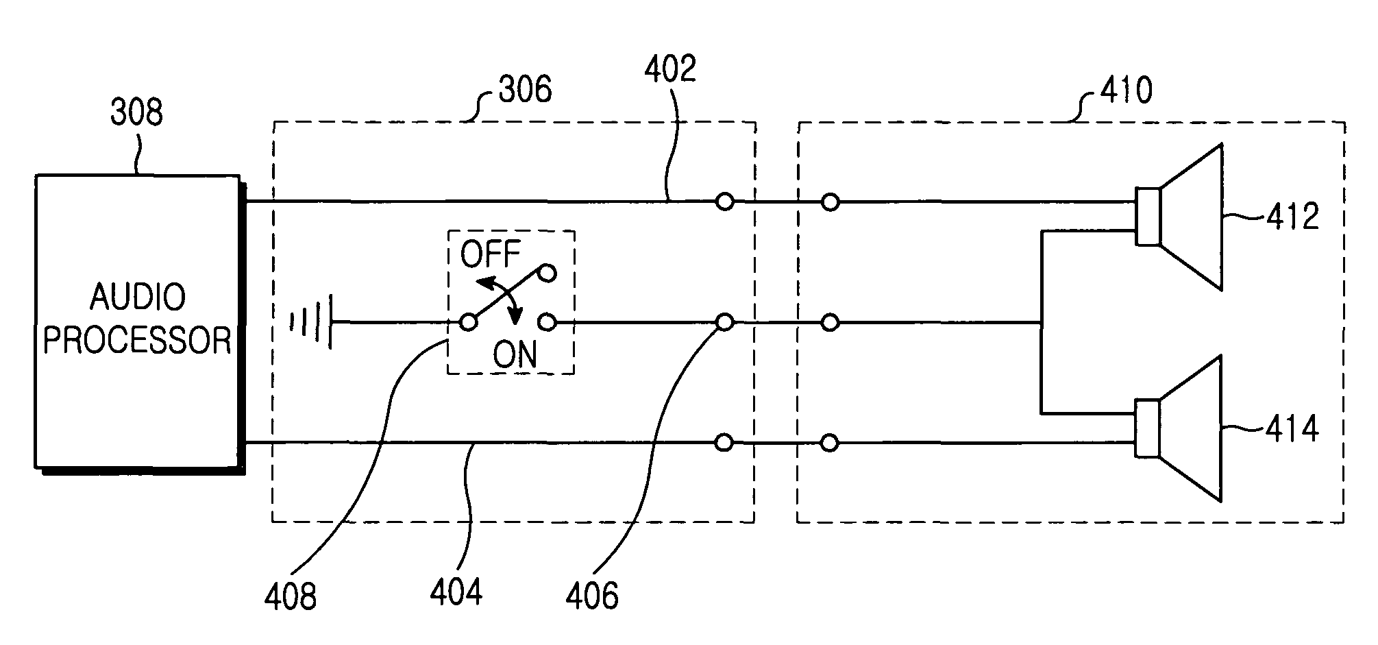
[0030]FIG. 3 is a block diagram illustrating an exemplary mo...


PUM


Abstract

An earphone jack for a mobile communication terminal and a driving method thereof, wherein the earphone jack includes a first speaker terminal for providing a positive (+) differential call voice signal when a call voice signal is output, a second speaker terminal for providing a negative (−) differential call voice signal when the call voice signal is output, and a switchable ground terminal for maintaining a ground on state when a media sound source is output, and becoming a ground off state when the call voice signal is output. The method includes the steps of determining whether an audio signal to be currently output is a media sound source signal (that is, a sound source media data signal), or a call voice signal (that is, a wireless call voice signal), and when the media sound source signal is output, maintaining a ground on state and outputting the media sound source signal in stereo, and when the call voice signal is output, maintaining a ground off state and outputting a differential signal.

Description

CROSS-REFERENCE TO RELATED APPLICATIONS[0001]This application claims the benefit under 35 U.S.C. §119(a) of Korean Patent Application No. 10-2004-0113740 entitled “Earphone Jack For Eliminating Power Noise In Mobile Communication Terminal, And Operating Method Thereof” filed in the Korean Intellectual Property Office on Dec. 28, 2004, the entire disclosure of which is incorporated herein by reference.BACKGROUND OF THE INVENTION[0002]1. Field of the Invention[0003]The present invention relates generally to an earphone jack for improving a call quality in a mobile communication terminal, and an operating method thereof. More particularly, the present invention relates to an earphone jack for eliminating power noise interference in a voice call, thereby improving a signal-to-noise ratio (SNR), and an operating method thereof.[0004]2. Description of the Related Art[0005]In general, an earphone is a device for allowing a user to hear a media sound source signal from a media-recording med...

Claims


Application Information

Patent Timeline
Patent Type & Authority Patents(United States)
IPC IPC(8): H04M1/00H04R3/00H04B1/08
CPCH04M1/6058H04B1/40H04R1/10H04R3/00
Inventor CHOI, KYU-SIC
Owner SAMSUNG ELECTRONICS CO LTD
Why Eureka
Try Eureka