Controller for eliminating acoustic noise of a power converter and related method thereof

a technology of power converters and controllers, which is applied in the direction of electric variable regulation, process and machine control, instruments, etc., can solve the problems of poor power saving of prior art, annoying acoustic noise generated by power converters, and poor control design of controllers. achieve the effect of reducing the resistance of compensation resistors, reducing the resistance of resistances, and reducing nois

Active Publication Date: 2017-02-28
LEADTREND TECH
View PDF10 Cites 0 Cited by
  • Summary
  • Abstract
  • Description
  • Claims
  • Application Information

AI Technical Summary

Benefits of technology

[0006]A first embodiment of the present invention provides a controller for eliminating acoustic noise of a power converter. The controller includes a feedback pin, a current detection pin, a burst mode signal generation module, a gate signal generation unit, and a turning-on time generation unit. The feedback pin is used for receiving a feedback voltage from a secondary side of the power converter, wherein the feedback voltage corresponds to an output voltage of the secondary side of the power converter. The current detection pin is used for generating a detection voltage according to a current flowing through a primary side of the power converter and a resistor. The burst mode signal generation module is coupled to the feedback pin for generating a burst mode signal according to a first reference voltage and the feedback voltage, or according to a second reference voltage and the feedback voltage. The gate signal generation unit is coupled to the burst mode signal generation module for generating a gate control signal corresponding to a burst mode of the power converter to a power switch of the primary side of the power converter according to the burst mode signal, wherein the power switch is turned on according to the gate control signal. The turning-on time generation unit is coupled to the burst mode signal generation module, the current detection pin, and the gate signal generation unit for determining a turning-on time of the power converter in the burst mode of the power converter according to the first reference voltage and the detection voltage, or according to the second reference voltage and the detection voltage.
[0007]A second embodiment of the present invention provides a controller for eliminating acoustic noise of a power converter. The controller includes a control unit and a gate signal generation unit. The control unit is used for detecting a frequency corresponding to a gate control signal in a burst mode of the power converter, wherein when the frequency is greater than a predetermined frequency, the control unit increases a resistance of a compensation resistor coupled to a feedback pin of the power converter, and when the frequency is less than the predetermined frequency, the control unit decreases the resistance of the compensation resistor. The gate signal generation unit is coupled to the control unit for generating the gate control signal to a power switch of a primary side of the power converter according to the resistance of the compensation resistor, wherein the power switch is turned on according to the gate control signal.
[0008]A third embodiment of the present invention provides a method for eliminating acoustic noise of a power converter, wherein a controller applied to the method includes a feedback pin, a current detection pin, a burst mode signal generation module, a turning-on time generation unit, and a gate signal generation unit, wherein the burst mode signal generation module includes a first comparator, a second comparator, and a control unit. The method includes the feedback pin receiving a feedback voltage from a secondary side of the power converter, wherein the feedback voltage corresponds to an output voltage of the secondary side of the power converter; the current detection pin generating a detection voltage according to a current flowing through a primary side of the power converter and a resistor; the burst mode signal generation module generating a burst mode signal according to a first reference voltage and the feedback voltage, or according to a second reference voltage and the feedback voltage; the turning-on time generation unit determining a turning-on time of the power converter in a burst mode of the power converter according to the first reference voltage and the detection voltage, or according to the second reference voltage and the detection voltage; and the gate signal generation unit generating a gate control signal corresponding to the burst mode of the power converter to a power switch of the primary side of the power converter according to the burst mode signal, wherein the power switch is turned on according to the gate control signal.
[0009]A fourth embodiment of the present invention provides a method for eliminating acoustic noise of a power converter, wherein a controller applied to the method includes a control unit and a gate signal generation unit. The method includes the control unit detecting a frequency corresponding to a gate control signal generated by the gate signal generation unit in a burst mode of the power converter; the control unit increasing a resistance of a compensation resistor coupled to a feedback pin of the power converter when the frequency is greater than a predetermined frequency; and the gate signal generation unit generating the gate control signal to a power switch of a primary side of the power converter according to the resistance of the compensation resistor, wherein the power switch is turned on according to the gate control signal.
[0010]The present invention provides a controller for eliminating acoustic noise of a power converter and a related method thereof. The controller and the method utilize a control unit to detect a frequency corresponding to a gate control signal generated by a gate signal generation unit, wherein when the frequency corresponding to the gate control signal is greater than a predetermined frequency, the controller and the method utilize a burst mode signal generation module, a turning-on time generation unit, the gate signal generation unit, a first reference voltage, a feedback voltage corresponding to an output voltage of a secondary side of the power converter, and a detection voltage corresponding to a current flowing through a primary side of the power converter to increase the frequency corresponding to the gate control signal; when the frequency corresponding to the gate control signal is less than the predetermined frequency, the controller and the method utilize the burst mode signal generation module, the turning-on time generation unit, the gate signal generation unit, a second reference voltage, the feedback voltage, and the detection voltage to decrease the frequency corresponding to the gate control signal. In addition, the controller and the method can also utilize the control unit to detect the frequency corresponding to the gate control signal generated by the gate signal generation unit, wherein when the frequency corresponding to the gate control signal is greater than the predetermined frequency, the controller and the method utilize the control unit to increase a resistance of a compensation resistor coupled to a feedback pin of the power converter, resulting in the frequency corresponding to the gate control signal being increased; and when the frequency corresponding to the gate control signal is less than the predetermined frequency, the controller and the method utilize the control unit to decrease the resistance of the compensation resistor coupled to the feedback pin of the power converter, resulting in the frequency corresponding to the gate control signal being decreased. Therefore, the present invention can ensure that the frequency corresponding to the gate control signal can fall outside a human auditory frequency range to eliminate acoustic noise of the power converter.

Problems solved by technology

When a frequency corresponding to the gate control signal generated by the controller falls within a human auditory frequency range, the power converter will generate annoying acoustic noise.
However, the prior art for eliminating acoustic noise of the power converter has poorer power saving, more complicated circuits, larger area, larger ripples in an output voltage of the power converter, and so on.
Therefore, the prior art is not a good choice for a designer of the controller.

Method used


Image

  • Controller for eliminating acoustic noise of a power converter and related method thereof
  • Controller for eliminating acoustic noise of a power converter and related method thereof
  • Controller for eliminating acoustic noise of a power converter and related method thereof

Examples


first embodiment

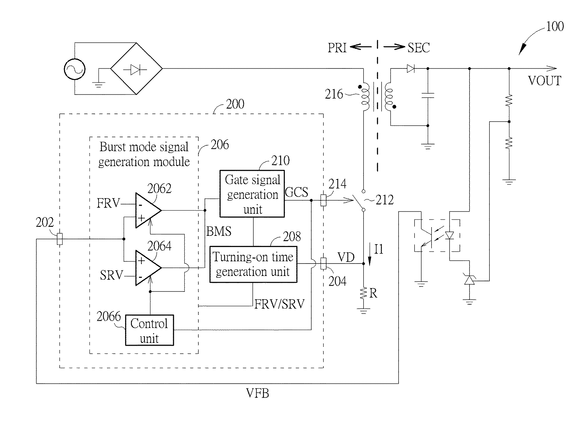
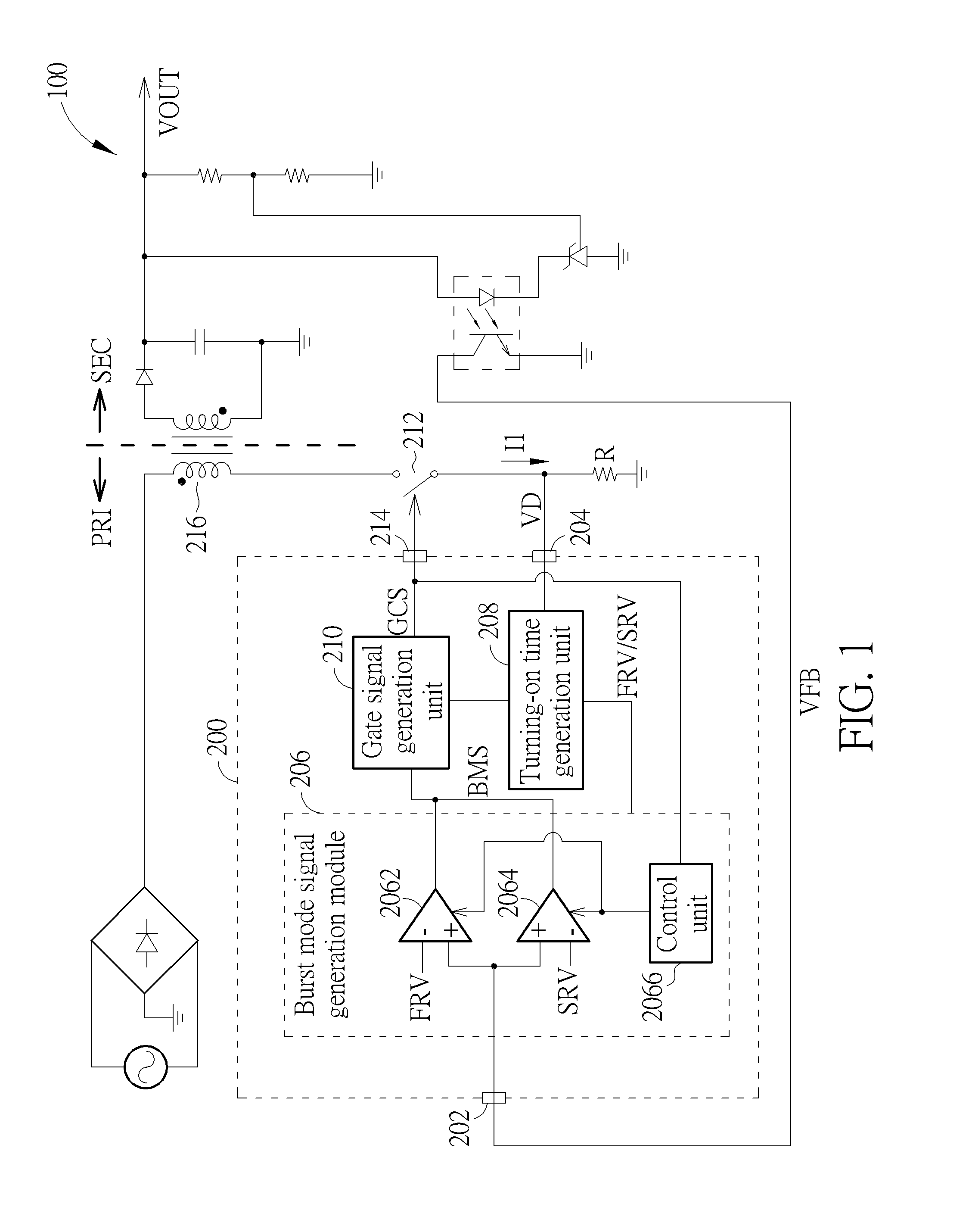
[0018]Please refer to FIG. 1. FIG. 1 is a diagram illustrating a controller 200 for eliminating acoustic noise of a power converter 100 according to a As shown in FIG. 1, the controller 200 includes a feedback pin 202, a current detection pin 204, a burst mode signal generation module 206, a turning-on time generation unit 208, and a gate signal generation unit 210, wherein the burst mode signal generation module 206 includes a first comparator 2062, a second comparator 2064, and a control unit 2066. The feedback pin 202 is used for receiving a feedback voltage VFB from a secondary side SEC of the power converter 100, wherein the feedback voltage VFB corresponds to an output voltage VOUT of the secondary side SEC of the power converter 100. The current detection pin 204 is used for generating a detection voltage VD according to a current I1 flowing through a primary side PRI of the power converter 100 and a resistor R. The burst mode signal generation module 206 is coupled to the f...

second embodiment

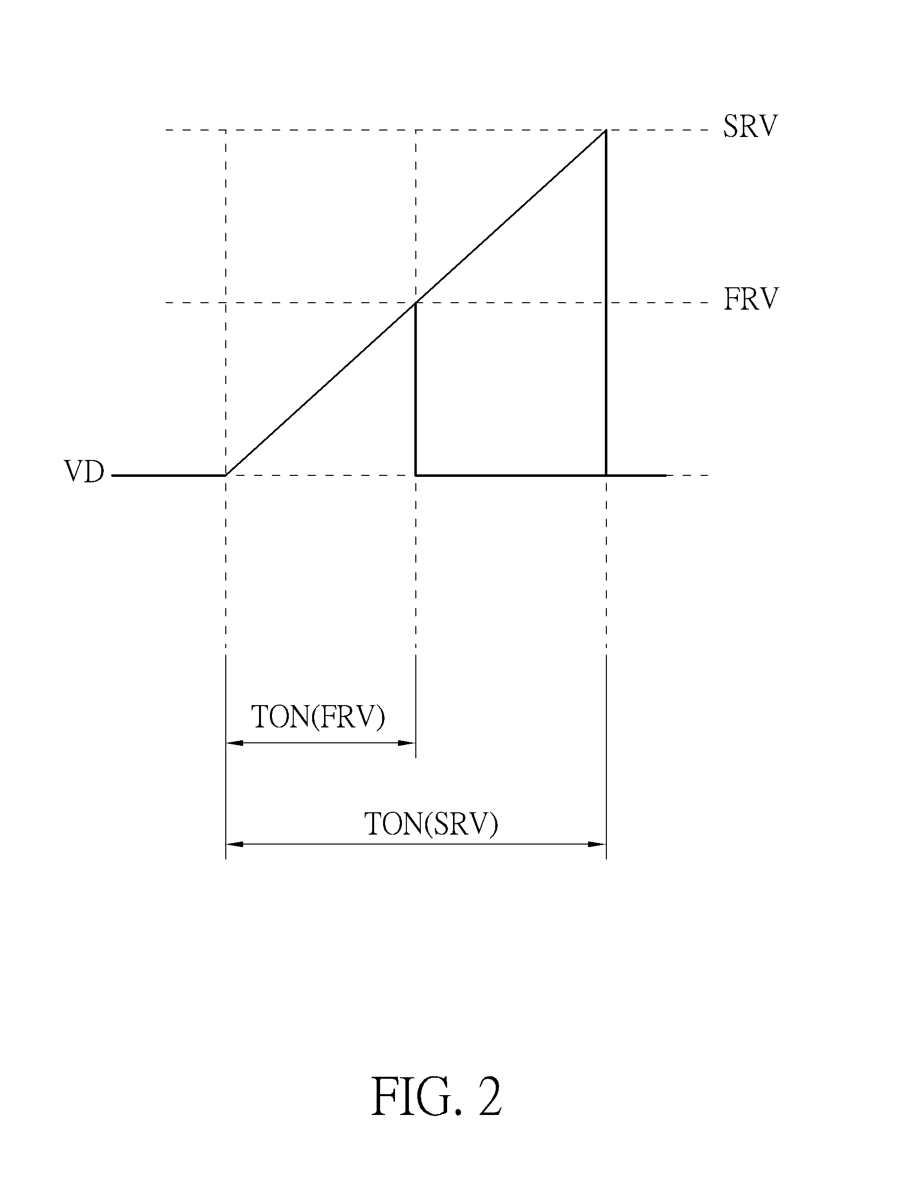
[0022]Please refer to FIG. 1, FIG. 2, and FIG. 4. FIG. 4 is a flowchart illustrating a method for eliminating acoustic noise of a power converter according to a The method in FIG. 4 is illustrated using the controller 100 in FIG. 1. Detailed steps are as follows:

[0023]Step 400: Start.

[0024]Step 402: The feedback pin 202 receives the feedback voltage VFB from the secondary side SEC of the power converter 100.

[0025]Step 404: The current detection pin 204 generates the detection voltage VD according to the current I1 flowing through the primary side PRI of the power converter 100 and the resistor R.

[0026]Step 406: The control unit 2066 detects the frequency FB corresponding to the gate control signal GCS generated by the gate signal generation unit 210.

[0027]Step 408: If the frequency FB corresponding to the gate control signal GCS is greater than the predetermined frequency; if yes, go to Step 410 and Step 412; if no, go to Step 414 and Step 416.

[0028]Step 410: The control unit 2066 ...

third embodiment

[0036]Please refer to FIG. 5. FIG. 5 is a diagram illustrating a controller 500 for eliminating acoustic noise of the power converter 100 according to a As shown in FIG. 5, a difference between the controller 500 and the controller 200 is that the controller 500 includes a control unit 502 and a gate signal generation unit 504. As shown in FIG. 5, the control unit 502 is used for detecting the frequency FB corresponding to the gate control signal GCS in the burst mode of the power converter 100; and the gate signal generation unit 504 is coupled to the control unit 502 for generating the gate control signal GCS to the power switch 212 of the primary side PRI of the power converter 100 according to a resistance of a compensation resistor RCOMP coupled to the feedback pin 202 of the power converter 100, wherein the power switch 212 can be turned on according to the gate control signal GCS.

[0037]Because a direct current (DC) gain DG of the power converter 100 is determined according t...


PUM


Abstract

A controller for eliminating acoustic noise of a power converter includes a control unit and a gate signal generation unit. The control unit is used for detecting a frequency corresponding to a gate control signal in a burst mode of the power converter. When the frequency is greater than a predetermined frequency, the control unit increases a resistance of a compensation resistor coupled to a compensation pin of the power converter; and when the frequency is less than the predetermined frequency, the control unit decreases the resistance of the compensation resistor. The gate signal generation unit is coupled to the control unit for generating the gate control signal to a power switch of a primary side of the power converter according to the resistance of the compensation resistor. The power switch is turned on according to the gate control signal.

Description

BACKGROUND OF THE INVENTION[0001]1. Field of the Invention[0002]The present invention relates to a controller for eliminating acoustic noise of a power converter and a related method thereof, and particularly to a controller and a related method thereof that can increase a frequency corresponding to a gate control signal when the frequency corresponding to the gate control signal is greater than a predetermined frequency, and decrease the frequency corresponding to the gate control signal when the frequency corresponding to the gate control signal is less than the predetermined frequency to eliminate acoustic noise of a power converter.[0003]2. Description of the Prior Art[0004]When a secondary side of a power converter is coupled to a light load, a controller applied to the power converter can generate agate control signal corresponding to a burst mode of the power converter to a power switch of a primary side of the power converter, wherein the power switch is turned according to ...

Claims


Application Information

Patent Timeline
Patent Type & Authority Patents(United States)
IPC IPC(8): H02M3/335H02M1/44H02M1/00
CPCH02M3/33507H02M1/44H02M2001/0035Y02B70/16H02M1/0035Y02B70/10
Inventor TSOU, MING-CHANGTSAI, MENG-JEN
Owner LEADTREND TECH
Why Eureka
Try Eureka