Thermal flow meter

a flow meter and flow rate technology, applied in the direction of volume/mass flow measurement, measurement devices, instruments, etc., can solve the problems of affecting the accuracy of flow measurement, variation and error of flow measurement, undesirable stress on the capillary tube, etc., to reduce heat conduction, minimize thermal gradient, and reduce heat conduction

Active Publication Date: 2010-07-06
BROOKS INSTRUMENT
View PDF13 Cites 25 Cited by
  • Summary
  • Abstract
  • Description
  • Claims
  • Application Information

AI Technical Summary

Benefits of technology

[0013]An object of the invention, therefore, is to provide an improved MFC with a novel sensor housing that reduces heat conduction from the housing base to the sensor itself. Another object of the invention is to minimize the thermal gradient that can result from the uneven application of heat to the housing base. A thermal mass flow controller or mass flow meter according to the present invention provides a novel sensor housing that reduces heat conduction from the housing mounting plate or base to the sensor itself. The housing also greatly minimizes the thermal gradient that can result from the uneven application of heat to the housing base. This reduction is accomplished in part by the use of one or more thermal isolation slots to isolate the upper portion of the housing (which holds the sensor) from the lower portion of the housing. In some embodiments, heat transfer to the sensor housing is also minimized by raising the middle portion of the bottom of the housing so that thermal contact is made between the base and the housing only at the two ends of the housing.

Problems solved by technology

A fundamental problem with typical MFCs is that, due to the operating principal of the flow sensor, external temperature differentials can greatly impact the accuracy of the flow measurement.
Because the flow sensor actually operates by responding to a heat / resistance difference between the two coils, a temperature gradient across the flow sensor will be interpreted as fluid flow and will result in variations and errors in flow measurements.
This flex can cause undesirable stress on the capillary tube.
As the base is tightened down onto the block, this tends to cause the base to flex.
If the sensor housing is only attached to the base at one center point, flexure of the base can cause an unacceptable stress on the two ends of the capillary tube.
Further, the Ambrosina design may reduce the actual gradient on the housing (and thus the sensor) but it does not sufficiently reduce the total heat conduction from the base.

Method used


Image

  • Thermal flow meter
  • Thermal flow meter
  • Thermal flow meter

Examples


Embodiment Construction

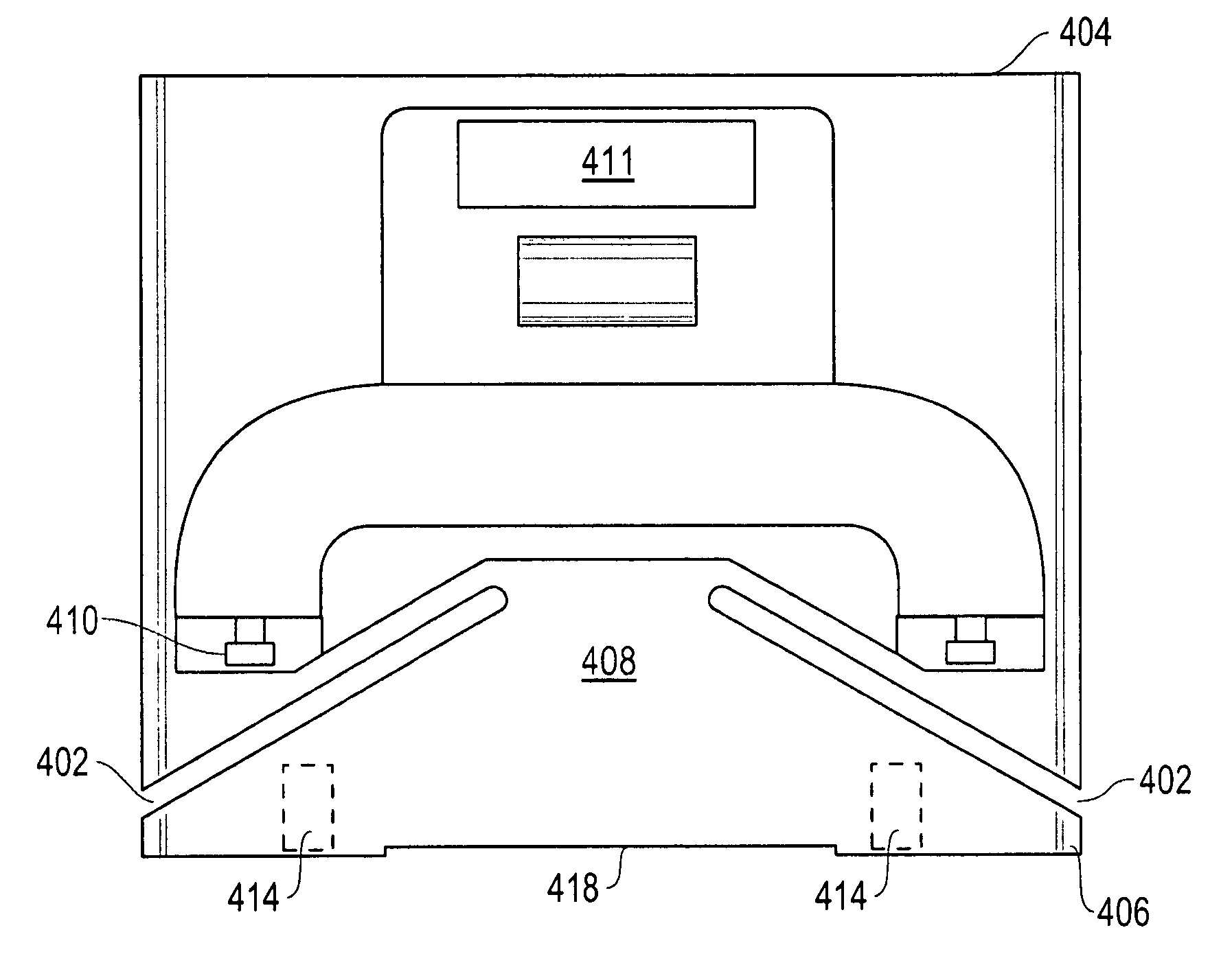
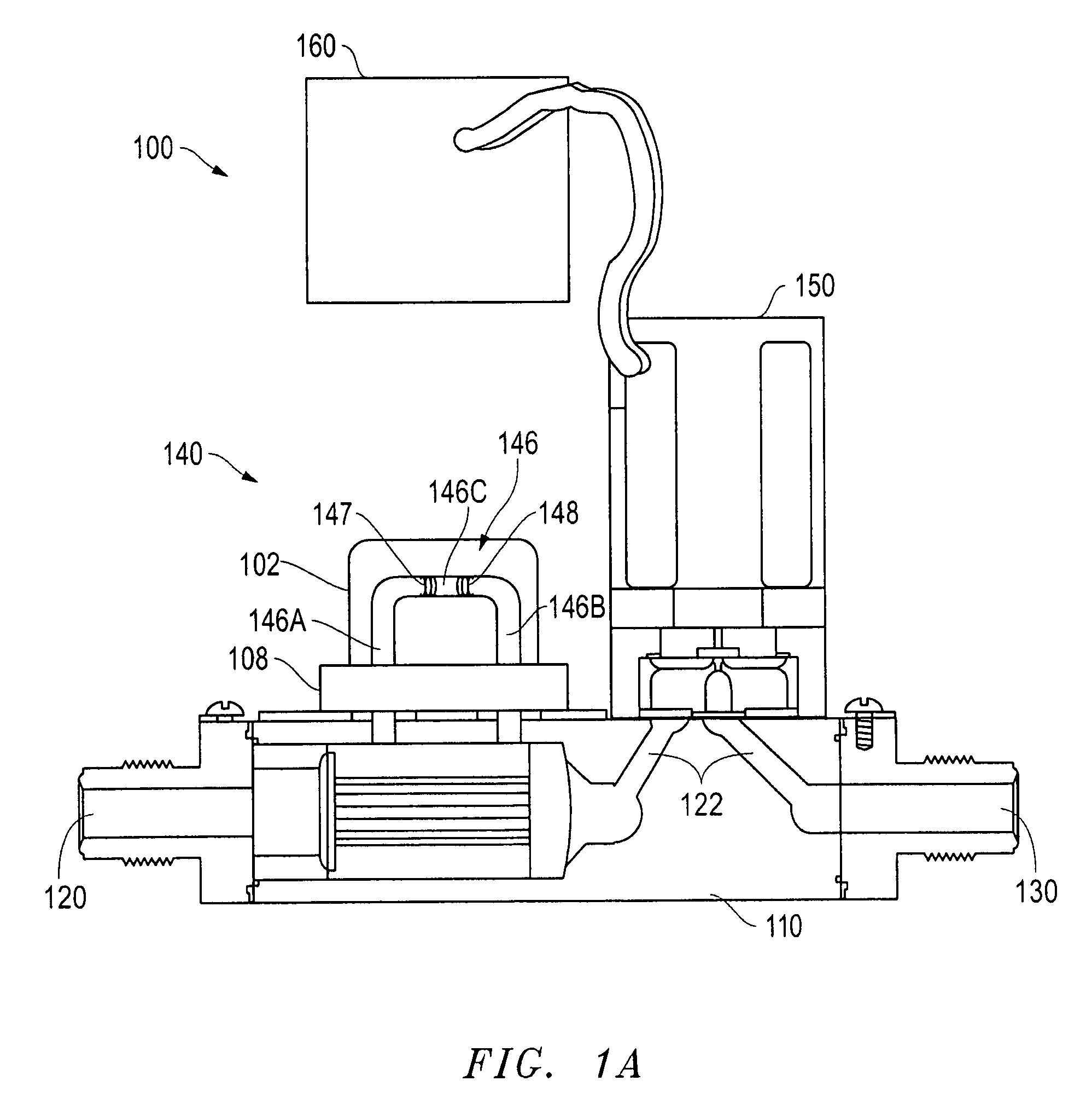
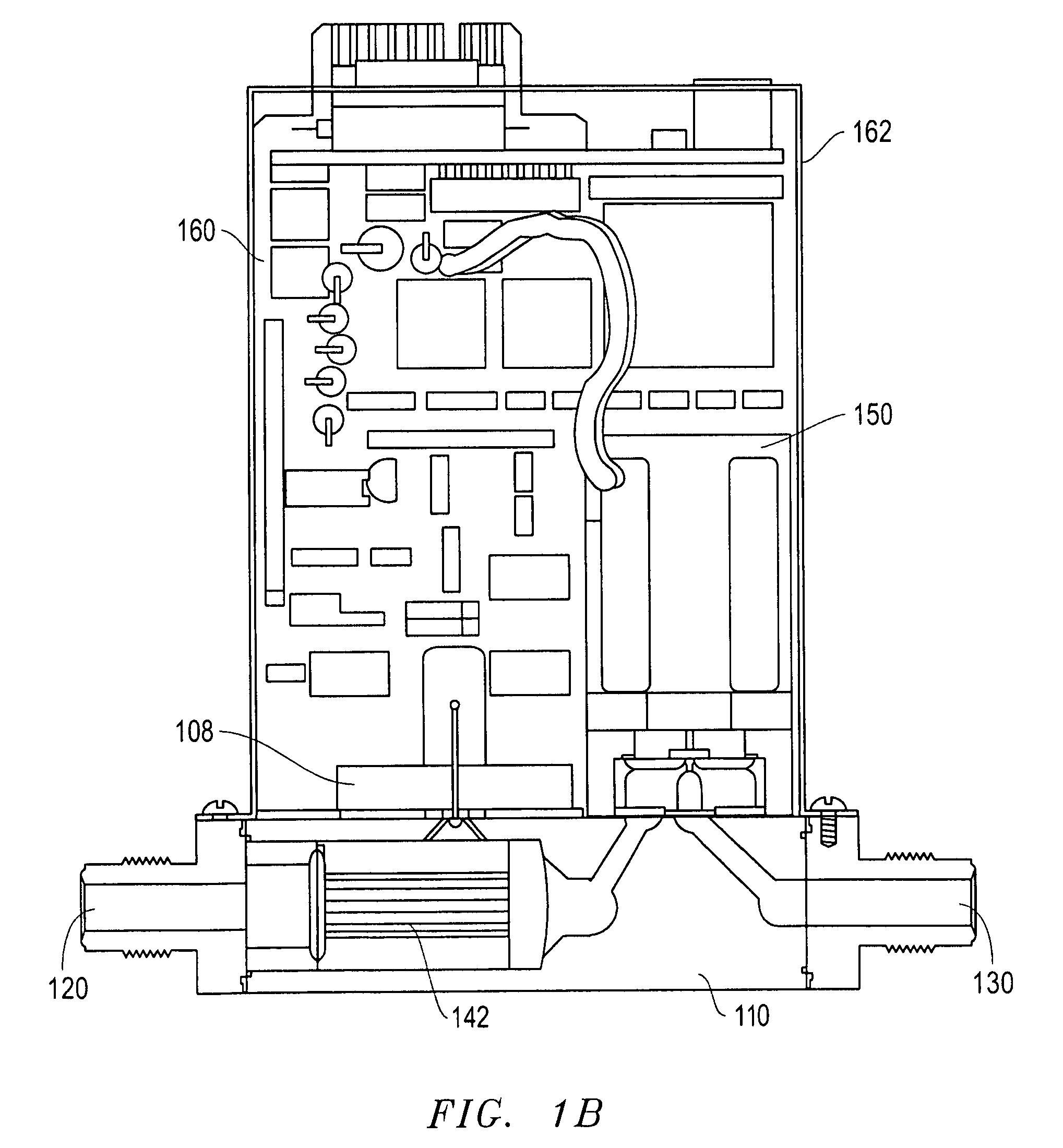
[0028]A thermal mass flow controller or mass flow meter according to the present invention provides a novel sensor housing that reduces heat conduction from the housing mounting plate or base to the sensor itself. The housing also greatly minimizes the thermal gradient that can result from the uneven application of heat to the housing base. This reduction is accomplished in part by the use of one or more thermal isolation slots to isolate the upper portion of the housing (which holds the sensor) from the lower portion of the housing. Heat transfer to the sensor housing is also minimized by raising the middle portion of the bottom of the housing so that thermal contact is made between the base and the housing only at the two ends of the housing.

[0029]Various embodiments and aspects thereof will now be described in more detail with reference to the accompanying FIGS. A preferred method or apparatus of the present invention has many novel aspects. Because the invention can be embodied ...


PUM


Abstract

A thermal mass flow controller or mass flow meter having a novel sensor housing that reduces heat conduction from the housing mounting plate or base to the sensor itself. The housing also greatly minimizes the thermal gradient that can result from the uneven application of heat to the housing base. This reduction is accomplished in part by the use of one or more thermal isolation slots to isolate the upper portion of the housing (which holds the sensor) from the lower portion of the housing. Heat transfer to the sensor housing is also minimized by raising the middle portion of the bottom of the housing so that thermal contact is made between the base and the housing only at the two ends of the housing.

Description

[0001]This application claims priority from U.S. Provisional Application No. 61 / 080,270 filed on Jul. 13, 2008, which is hereby incorporated by reference.TECHNICAL FIELD OF THE INVENTION[0002]Aspects of the present invention are directed to the measurement and control of the rate of flow of a fluid, and more particularly to a thermal flow meter that reduces heat conduction to the thermal flow sensor and that minimizes the effects of a thermal gradient on the sensor.BACKGROUND OF THE INVENTION[0003]The manufacture of semiconductors typically requires precise control of fluids (e.g., gasses, liquids, gas-vapor mixes) throughout the manufacturing process. Measurement and regulation of fluid flow is typically achieved by the use of a thermal mass flow controller (MFC). The MFC has a flow meter or sensor, which generally operates by directing fluid flow through a capillary tube path that runs parallel to a bypass area of the main flow path. Two thermally sensitive resistors are wound aro...

Claims


Application Information

Patent Timeline
Patent Type & Authority Patents(United States)
IPC IPC(8): G01F1/68
CPCG01F1/684G01F15/005
Inventor LULL, JOHN MICHAELJHOTY, GAWTAM
Owner BROOKS INSTRUMENT
Why Eureka
Try Eureka