
Tissue dissociation device

a tissue dissociation and tissue technology, applied in the field of medical laboratory equipment, can solve the problems that the small food processor is not suitable for reducing tissue, and achieve the effect of dissociating tissu

Active Publication Date: 2010-07-06
BATTELLE MEMORIAL INST
View PDF3 Cites 27 Cited by
  • Summary
  • Abstract
  • Description
  • Claims
  • Application Information

AI Technical Summary

Benefits of technology

[0008]The present invention relates to a tissue dissociation device. The device includes a container having a sterile interior for holding the tissue to be dissociated and a liquid medium. The device also includes a movable dissociation element, inside the container, for engaging the tissue to cause dissociation of the tissue. The device also includes a resistive element, inside the container, for resisting movement of the tissue in response to the engagement by the dissociation element. The resistance provided by the resistive element allows the dissociation element to effectively dissociate the tissue.
[0011]The invention also relates to a method of producing a cell suspension using the tissue dissociation device. The tissue and a liquid medium are inserted into the container of the device. The tissue is engaged with the moving dissociation element of the device. The resistive element of the device resists movement of the tissue in response to the engagement by the dissociation element. The resistance provided by the resistive element allows the dissociation element to effectively dissociate the tissue into a cell suspension.

Problems solved by technology

This small food processor would not be suitable for reducing tissue to a single cell suspension while maintaining cell viability and sterility of the sample.
The blender is useful for mixing liquids and / or powders; it would not be suitable for reducing tissue to a single cell suspension while maintaining cell viability and sterility of the sample.

Method used


Image

  • Tissue dissociation device
  • Tissue dissociation device
  • Tissue dissociation device

Examples


Embodiment Construction

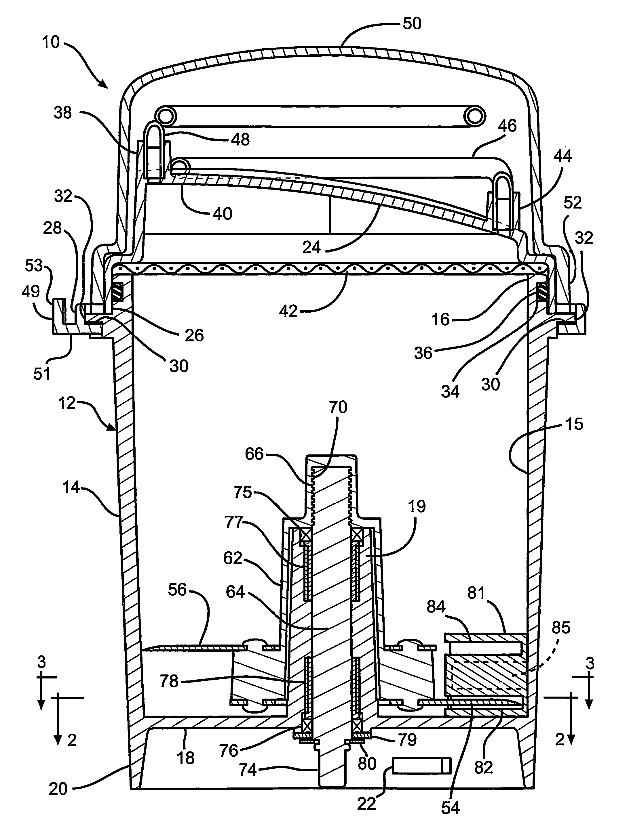
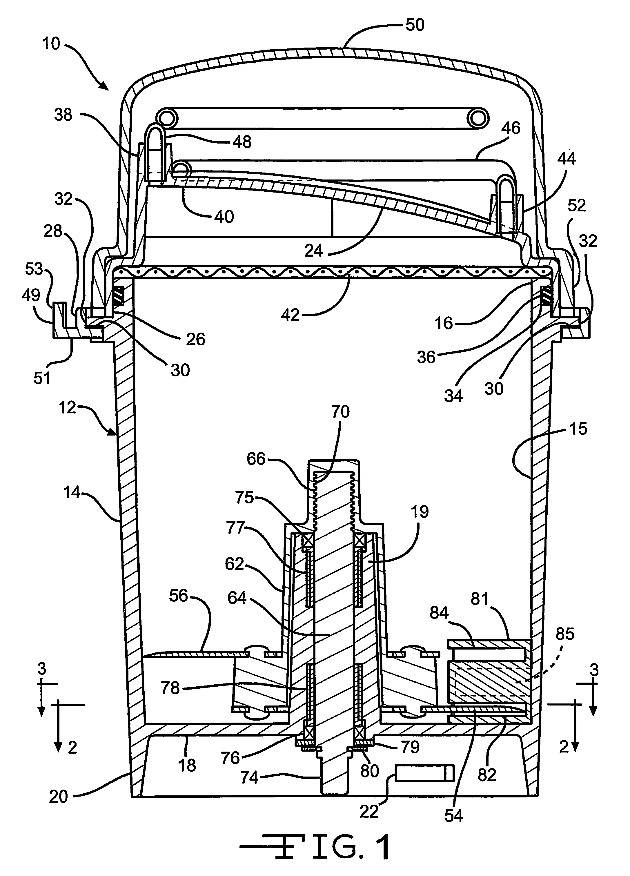
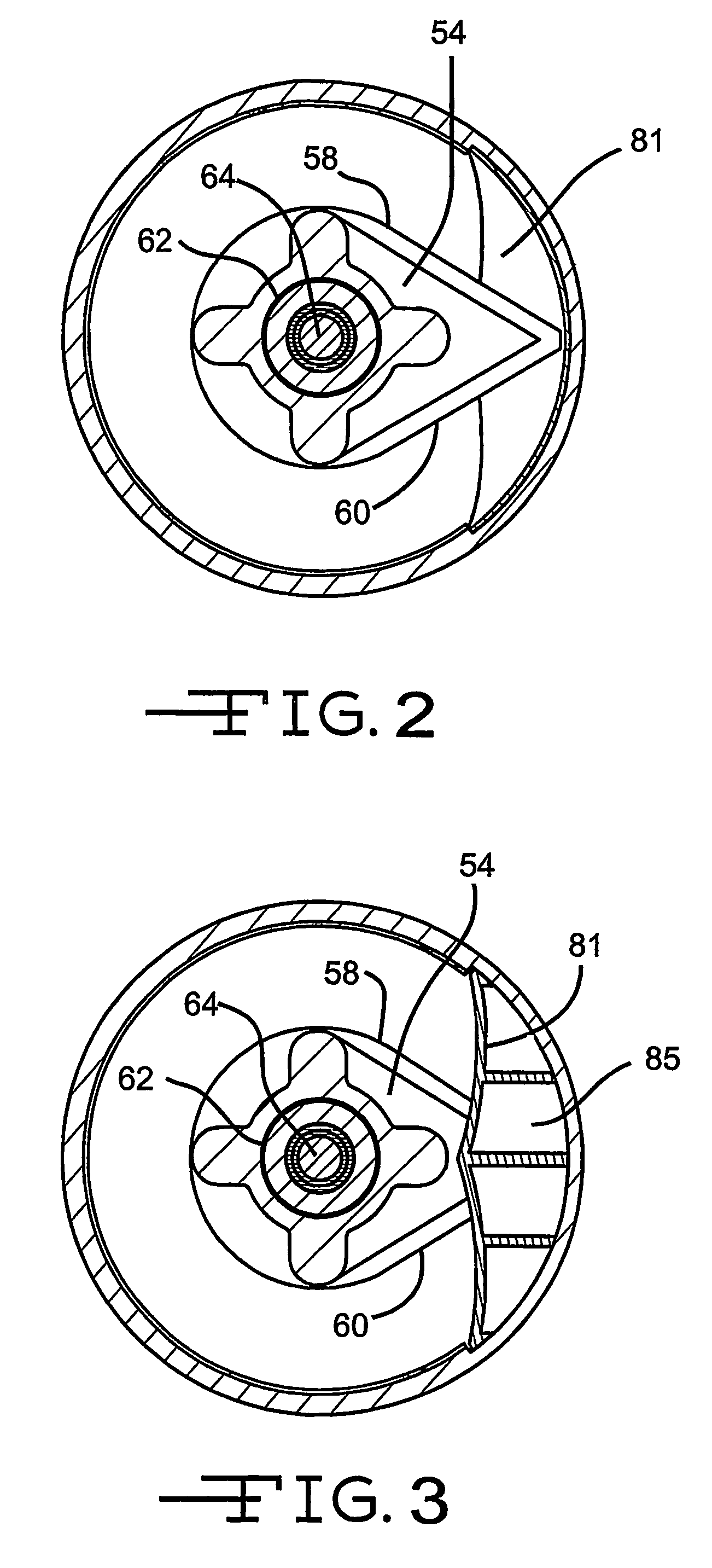
[0017]The present invention relates to a tissue dissociation device that is capable of dissociating biological tissue into a cell suspension. FIG. 1 illustrates a preferred embodiment of a tissue dissociation device 10 according to the invention. The device includes a container 12 for holding the tissue to be dissociated and a liquid medium. The container can have any suitable structure. In the illustrated embodiment, the container is cup-shaped, including a symmetrical outer wall 14 that is generally cylindrical in shape, an open upper end 16 and a closed lower end 18. The container has a sterile interior 15. In one embodiment, particularly useful with lung tumor cells, the container has a volume of from about 100 ml (about 6 cu inches) to about 1000 ml (about 60 cu inches). The size of the container may differ based on the type of tissue to be dissociated.

[0018]The container includes a tubular central hub 19 that extends upward inside the container from the lower end. The distance...


PUM

PropertyMeasurementUnit
velocityaaaaaaaaaa
lengthaaaaaaaaaa
volumeaaaaaaaaaa

Abstract

A tissue dissociation device (10) includes a container (12) having a sterile interior for holding the tissue to be dissociated and a liquid medium. The device (10) also includes a dissociation element (54), inside the container (12), for engaging the tissue to cause dissociation of the tissue. The device (10) also includes a resistive element (81), inside the container (12), for resisting movement of the tissue in response to the engagement by the dissociation element (54). Relative motion between and the resulting resistance provided by the resistive element (81) allows the dissociation element (54) to effectively dissociate the tissue. A powered tissue dissociation device includes a power source operatively connected to the dissociation element (54) for causing the dissociation element (54) to move into engagement with the tissue.

Description

CROSS-REFERENCE TO RELATED APPLICATION[0001]This application claims the benefit of U.S. provisional application Ser. No. 60 / 504,772, filed Sep. 22, 2003.BACKGROUND OF THE INVENTION[0002]This invention relates in general to medical laboratory equipment, and in particular to a device for dissociating biological tissue.[0003]In the fields of medicine and biological research, it is often necessary to dissociate a biological tissue into a single cell suspension. For example, an individualized cancer vaccine can be produced using a cancer patient's own tumor cells. An initial step of the vaccine process is to dissociate a tumor removed from the patient into a single cell suspension. A variety of physical and chemical dissociation methods are known, including cutting, scraping, mincing, or perfusing the tissue, and digestion with enzymes or nonenzymatic solutions. There is still a need for a tissue dissociation device for reducing tissue to a single cell suspension while maintaining cell v...

Claims


Application Information

Patent Timeline
Patent Type & Authority Patents(United States)
IPC IPC(8): C12N9/00C12N5/02C12M1/00C12N5/00B02B5/02C12M3/08C12N1/02C12N5/07C12N5/071
CPCC12M45/02C12M45/04C12N1/02
Inventor BULLEN, LAWRENCEBRESLER, HERBERT S.KRAMER, DANIEL A.
Owner BATTELLE MEMORIAL INST
Learn More