Battery management system with predictive failure analysis

a technology of failure analysis and battery management system, applied in the field of large stationary battery management, can solve problems such as difficulty in managing, and achieve the effects of facilitating data transfer, easy management, and increasing voltage and output power

Inactive Publication Date: 2010-07-06
ASKALITY LLC
View PDF16 Cites 19 Cited by
  • Summary
  • Abstract
  • Description
  • Claims
  • Application Information

AI Technical Summary

Benefits of technology

[0008]The OMS® system can track batteries from cradle-to-grave. It enables companies with large deployments of stationary batteries to manage assets that are both perishable and geographically dispersed, and therefore difficult to manage. Batteries are usually deployed in “strings” of electrically interconnected jars or clusters to increase voltage and output power. Each battery test data point is stored along with the unique identifier value associated with the individual battery jar, or, alternatively, a unique identifier associated with an individual string. A “battery unit” is defined herein as either an individual battery jar or a battery string. Where the tags associated with the batteries are bar codes, the user would preferably connect a BatteryCorp BC-T2000 or BC Celltron Ultra or similar testing device to the serial port of a PC with the provided null-modem cable or by means of other compatible communication interface, whether wired or wirelessly connected. Linking software, preferably the T2000 Link or Celltron Receive Utility Software facilitates the transfer of data from the testing and data acquisition device preferably to a local data storage device. The user would then logs into the proprietary website and clicks on the Upload Data icon; the software would then upload the specified data file to a proprietary web server. The web server processes the data file, storing the pertinent data in the appropriate tables of a database. The data may also be uploaded wirelessly, as is well known in the art, via any of the wireless transmission apparatus and protocols available and compatible with the other system components.

Problems solved by technology

It enables companies with large deployments of stationary batteries to manage assets that are both perishable and geographically dispersed, and therefore difficult to manage.

Method used


Image

  • Battery management system with predictive failure analysis
  • Battery management system with predictive failure analysis
  • Battery management system with predictive failure analysis

Examples


Embodiment Construction

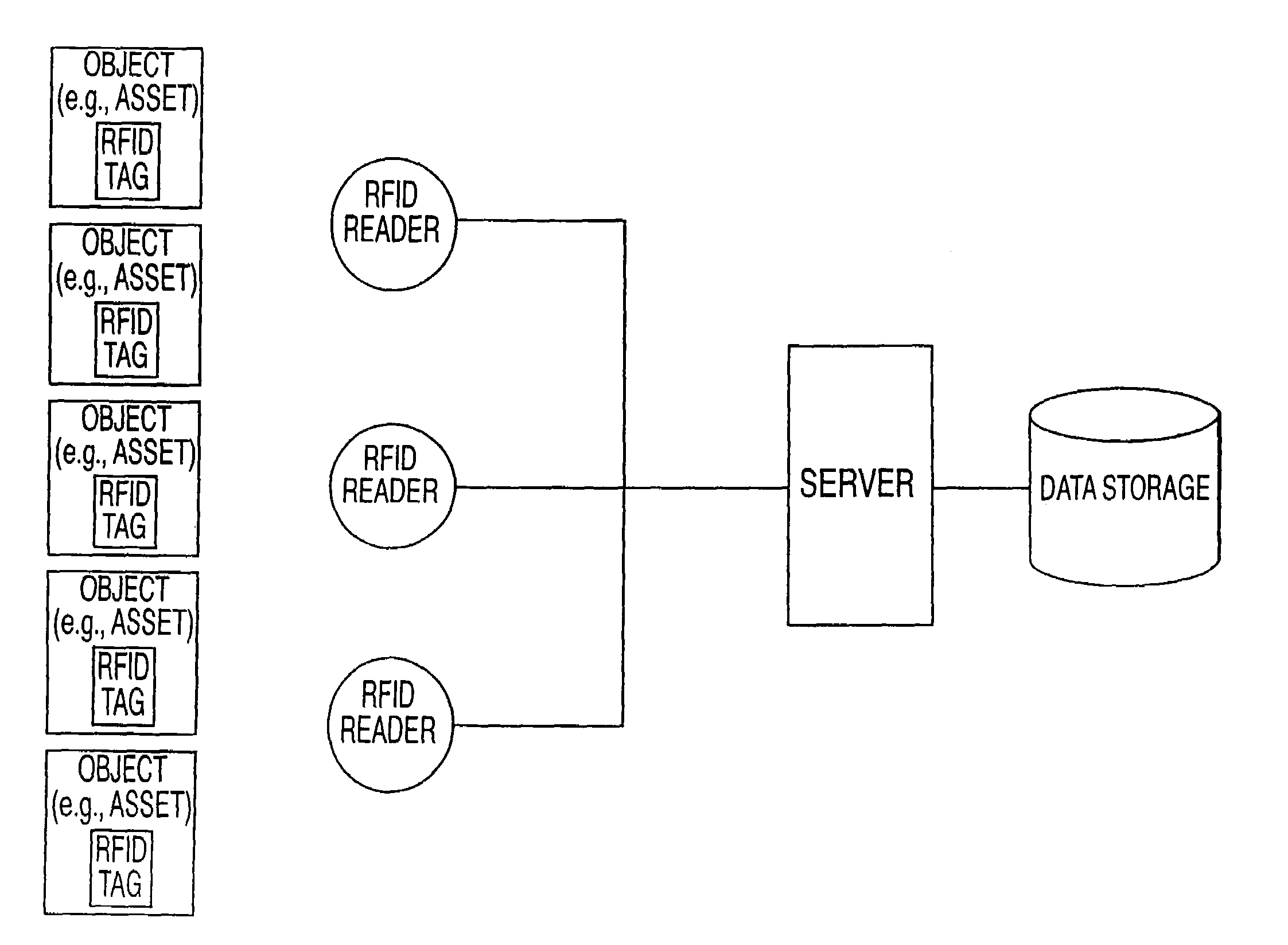
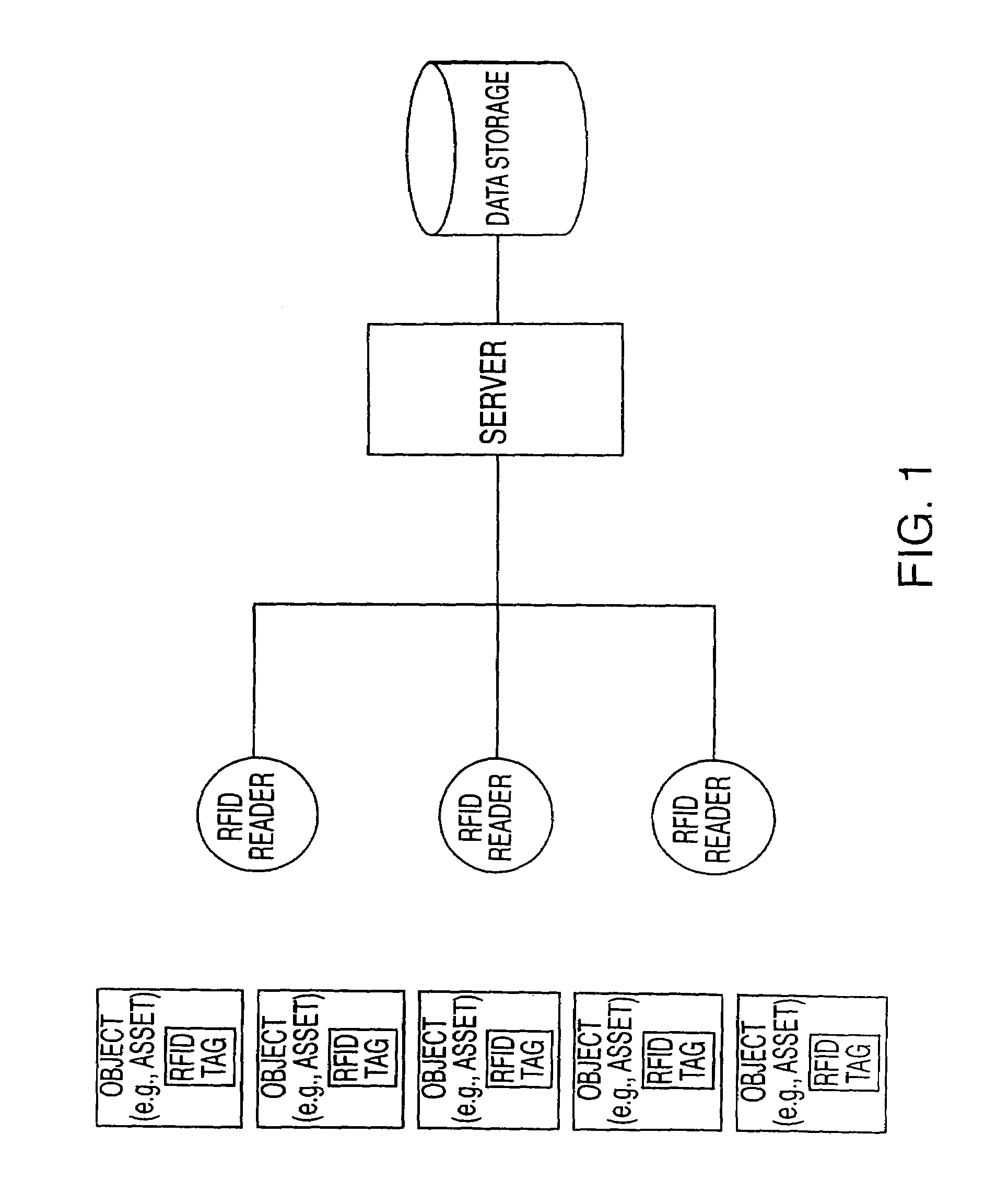
[0020]The invention provides and coordinates battery testing, maintenance, installation, fulfillment and disposal of batteries, and is capable of performing these functions over a wide geographical area. It seamlessly integrates these services via ohmic testing devices and the web based platform. This innovative solution helps companies improve their backup power systems while reducing costs. The system preferably employs Mega-Tags to be associated with an individual battery jar or with a battery string, a string here defined as a plurality of electrically connected battery jars, treating the battery string as a battery unit. The tag is associated with a particular battery unit, so that the unique identification number embedded in the tag is consistently associated with that particular battery unit.

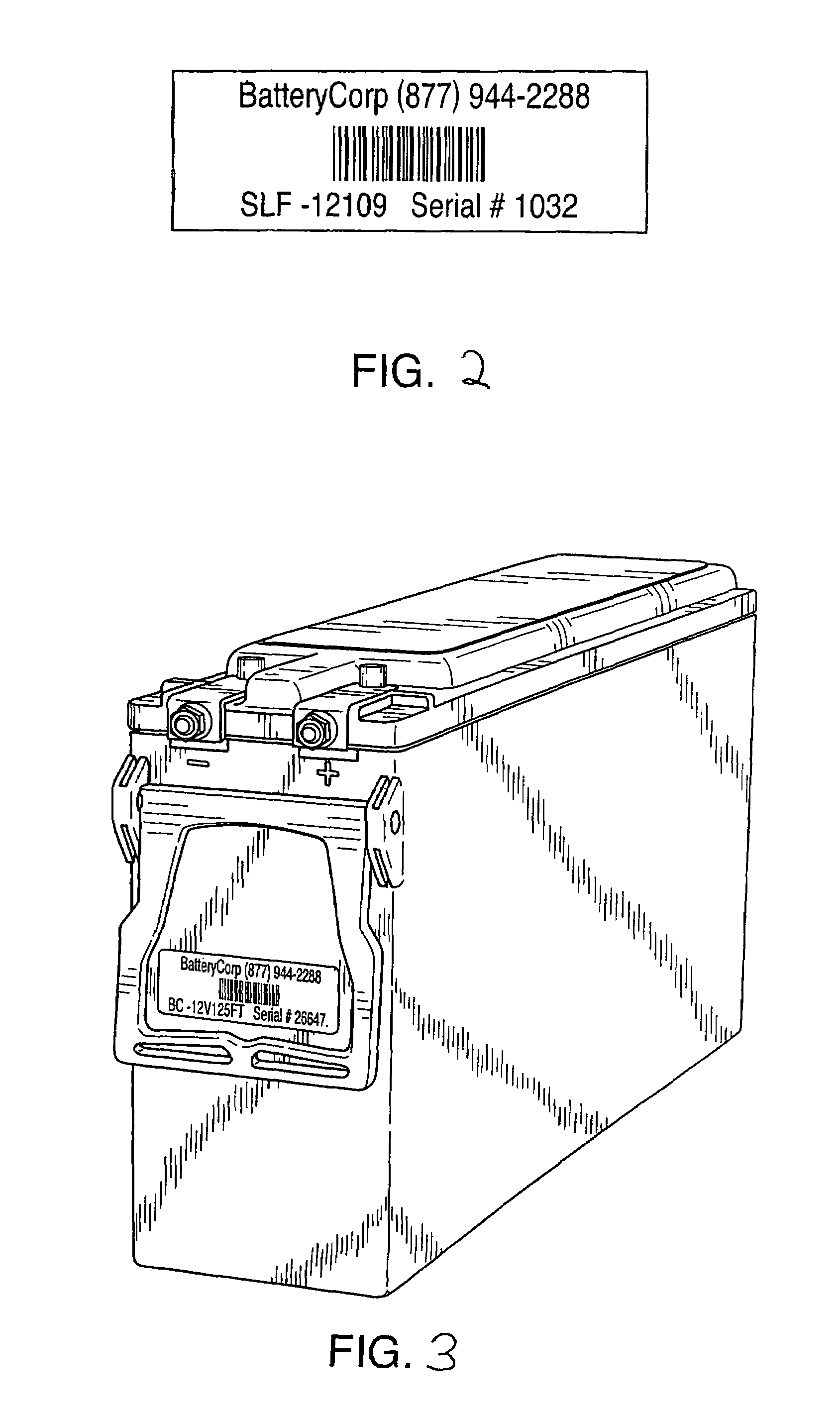
[0021]Mega-Tags are preferably bar coded labels or RFID tags that contain a unique identifier for the associated battery unit. FIG. 1 shows an RFID system, having an array of battery unit...


PUM

PropertyMeasurementUnit
impedanceaaaaaaaaaa
conductanceaaaaaaaaaa
resistanceaaaaaaaaaa

Abstract

The invention relates to the management of large stationary batteries. The invention is a comprehensive system and process for the management of stationary batteries that are used for backup power and are deployed in widely dispersed locations. The system is comprised of Mega-Tags, a battery testing and data acquisition device, and web-based software. The system software can automatically analyze, determine and report predicted battery failure data such as a future anticipated failure date by aging standard ohmic test values such as impedance, conductance, or resistance, by multiplying the test value by a monthly factor derived from statistical analysis and comparing the aged value to a baseline value to determine the predicted failure date.

Description

CROSS REFERENCE TO RELATED APPLICATIONS[0001]This application is a continuation-in-part of, and claims priority to, U.S. application Ser. No. 11 / 125,450, filed May 10, 2005, related to U.S. application Ser. No. 11 / 125,631, filed May 10, 2005, related to U.S. application Ser. No. 11 / 025,816, filed Dec. 29, 2004, related to U.S. application Ser. No. 11 / 025,305, filed Dec. 29, 2004, each of the foregoing applications being continuations-in-part of U.S. application Ser. No. 10 / 749,004, filed Dec. 30, 2003 (now U.S. Pat. No. 7,003,431, issued Feb. 21, 2006), and all of the foregoing being incorporated herein by reference in their entirety.BACKGROUND OF THE INVENTION[0002]The invention relates to the management of large stationary batteries, and incorporates a method of predictive battery failure analysis to enable users to more accurately estimate the useful life of a battery or series of batteries. The invention is preferably employed within a comprehensive system and apparatus for the ...

Claims


Application Information

Patent Timeline
Patent Type & Authority Patents(United States)
IPC IPC(8): G01N27/416G08B21/00
CPCG01R31/3648
Inventor QUINT, JONATHAN B.DWORKIN, STEVEN H.
Owner ASKALITY LLC
Why Eureka
Try Eureka