Flexible neural stimulation engine

a neural stimulation engine and flexible technology, applied in the field of cardiac pacemakers, neural stimulators, implantable cardioverters/defibrillators, can solve the problems of large amount of battery power consumed, systolic and diastolic dysfunction, and software pacing decisions inevitably introduce variability in the timing of paces, so as to achieve the effect of easy modification of device behavior

Active Publication Date: 2010-07-06
CARDIAC PACEMAKERS INC
View PDF33 Cites 89 Cited by
  • Summary
  • Abstract
  • Description
  • Claims
  • Application Information

AI Technical Summary

Benefits of technology

[0005]In an approach described herein, a bradycardia pacing mode is implemented using a brady table which maps particular device states, as defined by the occurrence of sensed events and the states of timers, to particular device actions such as the delivery of pacing pulses and the resetting or stopping of timers. Hardware-based circuitry compares the current state of the device to the device states contained in the brady table. If the current device state matches a table device state, the circuitry performs the actions to which the table device state is mapped. The brady table may be stored in an area of RAM, referred to as the brady RAM, which can be accessed by a microprocessor as well as the hardware-based circuitry. Device behavior may thus be easily changed by loading a different brady table into the brady RAM.

Problems solved by technology

Controlling the delivery of paces with a firmware-based system, however, also has some disadvantages.
If the microprocessor continually executes instructions during the cardiac cycle in order to process and respond to timing and sensing events, a large amount of battery power is consumed.
Also, making pacing decisions with software inevitably introduces some variability into the timing of the paces, commonly referred to as pacing jitter.
Although ventricular dilation and hypertrophy may at first be compensatory and increase cardiac output, the processes eventually result in both systolic and diastolic dysfunction.
As a result, the heart works harder to maintain flow at a higher blood pressure, which can contribute to heart failure.

Method used


Image

  • Flexible neural stimulation engine
  • Flexible neural stimulation engine
  • Flexible neural stimulation engine

Examples


Embodiment Construction

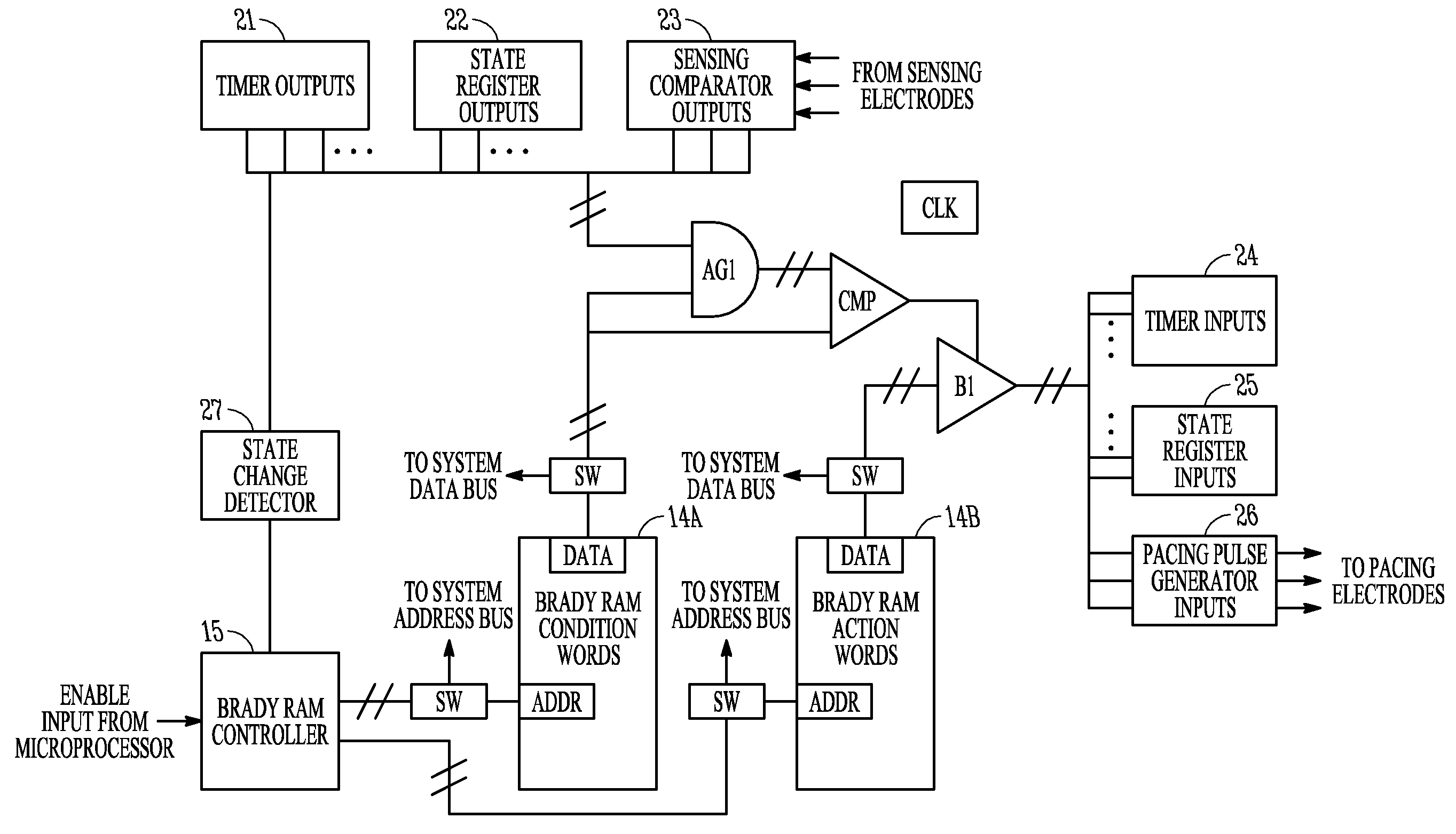
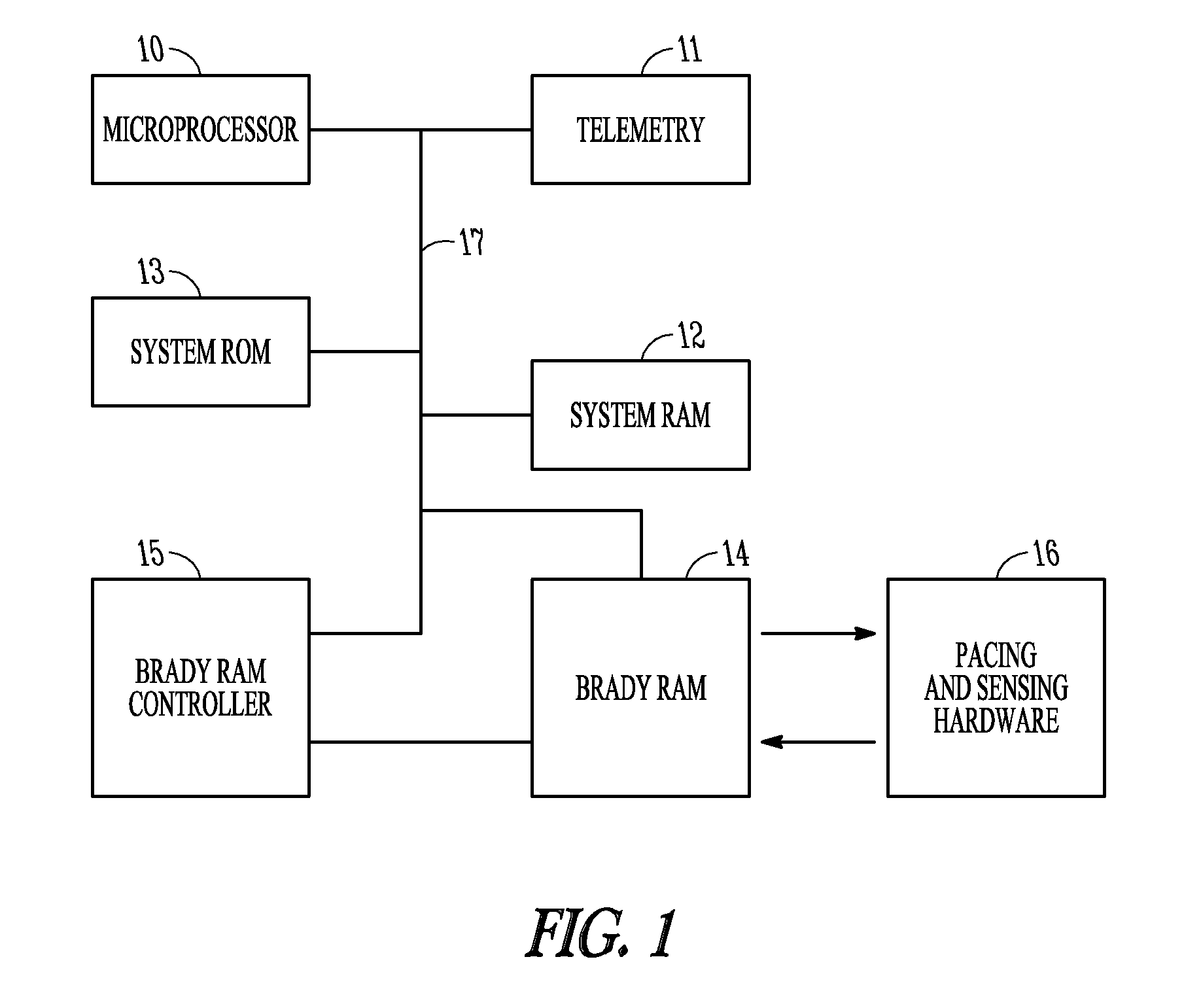
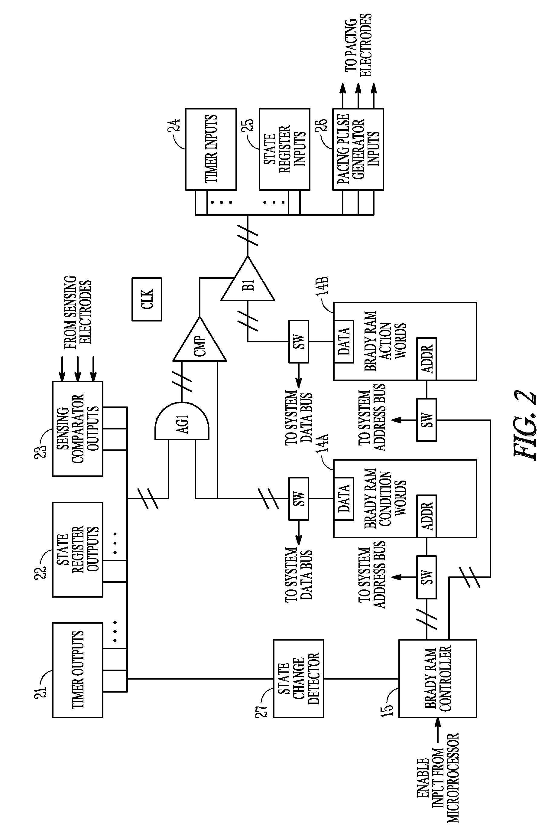
[0022]Described herein is a device and method, such as for implementing a bradycardia pacing mode which allows for a low power implementation that is mostly hardware-based but still allows the flexibility for making major changes in brady behavior normally found only in firmware-based implementations. The brady behavior of the device is encapsulated by a RAM-based table in an area of RAM referred to as brady RAM, and the brady behavior can be changed by re-loading the brady RAM with a different table. Firmware executed by a microprocessor may load the table based on the brady mode desired. Hardware then reads the table only when pacing decisions need to be made, and uses the information in the table to make brady decisions. The design may be easily extended to more complicated pacing modes by making the RAM larger. Because hardware rather than firmware decides when to pace, there is no latency in pace delivery, and no jitter in the cycle length. The device may also utilize a FIFO qu...


PUM


Abstract

An implantable medical device comprising stimulation circuitry adapted to provide neural stimulation energy to a neural stimulation electrode, one or more timers, including at least one neural event timer, a device behavior memory including a neural table, and a comparison circuit. The neural table maps a particular device state defined at least in part by a neural event timer to one or more associated device actions that include at least one of a neural stimulation energy delivery, a change in state of at least one neural event timer, and both a neural stimulation energy delivery and a change in state of one or more timers. The comparison circuit is adapted to compare a current state of one or more timers to a device state in the neural table and, if found to match, causing performance of one or more associated device actions.

Description

RELATED APPLICATIONS[0001]This document is a continuation-in-part of commonly assigned, co-pending, Yost et al. U.S. patent application Ser. No. 11 / 116,596, entitled “Cardiac Pacemaker with Table-Based Pacing Mode Implementation,” which was filed Apr. 28, 2005, in which is incorporated by reference herein.TECHNICAL FIELD[0002]This document pertains generally to the field of cardiac pacemakers, neural stimulators, and implantable cardioverter / defibrillators incorporating a pacing function. In particular, the document relates to the hardware and software used to control the operation of such devices.BACKGROUND[0003]It is now common for patients having disorders of cardiac rhythm to be treated with implantable pacemakers that provide electrical stimulation to selected chambers of the heart in the form of timed pacing pulses. The most common condition for which pacemakers are used is in the treatment of bradycardia, where the ventricular rate is too slow. Atrio-ventricular conduction de...

Claims


Application Information

Patent Timeline
Patent Type & Authority Patents(United States)
IPC IPC(8): A61N1/08
CPCA61N1/362A61N1/025A61N1/36125A61N1/36135A61N1/3682
Inventor TERNES, DAVIDBIRKHOLZ, DOUG M.YOST, DAVID W.ESLER, JAMES A.
Owner CARDIAC PACEMAKERS INC
Why Eureka
Try Eureka