Integrated circuit device

a technology of integrated circuits and circuits, applied in the direction of liquid/fluent solid measurement, process and machine control, instruments, etc., can solve the problems of not being able to deal with a complex power supply sequence, not being able to execute another power supply sequence without preparation, and not being able to execute a fixed sequence, etc., to reduce the time to restart the system, and low power consumption

Inactive Publication Date: 2010-07-06
RENESAS ELECTRONICS CORP
View PDF35 Cites 31 Cited by
  • Summary
  • Abstract
  • Description
  • Claims
  • Application Information

AI Technical Summary

Benefits of technology

[0011]According to one aspect of the present invention, there is provided an integrated circuit device that includes a processor having an arithmetic circuit and a power management unit implementing power control of the processor through a power supply section without having an arithmetic circuit. The power management unit includes a memory storing a plurality of commands and a control section implementing power control of the processor according to the commands stored in the memory. Since this integrated circuit device has the power management unit that implements power control of the processor, it is possible to issue an instruction to each peripheral macro even when no power is supplied to the processor, thereby reducing a time to restart the system. Further, the power management unit is programmable, and it is thus possible to execute various power-on / off sequences by changing the commands stored in the memory and to deal with a large number of power division splits. Furthermore, the power management unit allows easy function enhancement and change for command control. In addition, since the power management unit has no arithmetic circuit, the circuit size is significantly smaller than a processor having an arithmetic circuit, thereby achieving low power consumption.
[0012]According to another aspect of the present invention, there is provided an integrated circuit device that includes a processor having an arithmetic circuit and a programmable sequencer implementing power control of the processor through a power supply section without having an arithmetic circuit, wherein the programmable sequencer performs initialization of another circuit in the integrated circuit device in parallel with supplying power to the processor through the power supply section. This configuration allows reducing a time to restart the system.

Problems solved by technology

Further, as LSI becomes more complex, the proportion of static consumption current or leakage current that is consumed in stop state to entire consumption current rises so high that it is not negligible in a microfabrication process of 0.13 μm or less.
Further, since the control circuit 21 is configured by hardware, it can only execute a fixed sequence and cannot deal with a complex power supply sequence.
Even if such a complex power supply sequence can be executed by the hardware fixed circuit, it is not possible to execute another power supply sequence without preparation.
Furthermore, placing the circuits for executing various types of power supply sequences on a hardware fixed circuit increases the circuit size.
Therefore, this control circuit cannot execute a complex power supply sequence and is not flexible.
However, since the CPU has an arithmetic circuit, a considerable amount of leakage current occurs in spite of low power consumption and the effect of reducing power consumption is small.
As described in the foregoing, it has now been discovered that the conventional integrated circuit device cannot deal with a complex power supply sequence since it implements CPU power control with a hardware fixed circuit.
Further, the conventional technique that implements high performance CPU power control with a low power consumption CPU has only a small power consumption reduction effect.

Method used


Image

  • Integrated circuit device
  • Integrated circuit device
  • Integrated circuit device

Examples


first embodiment

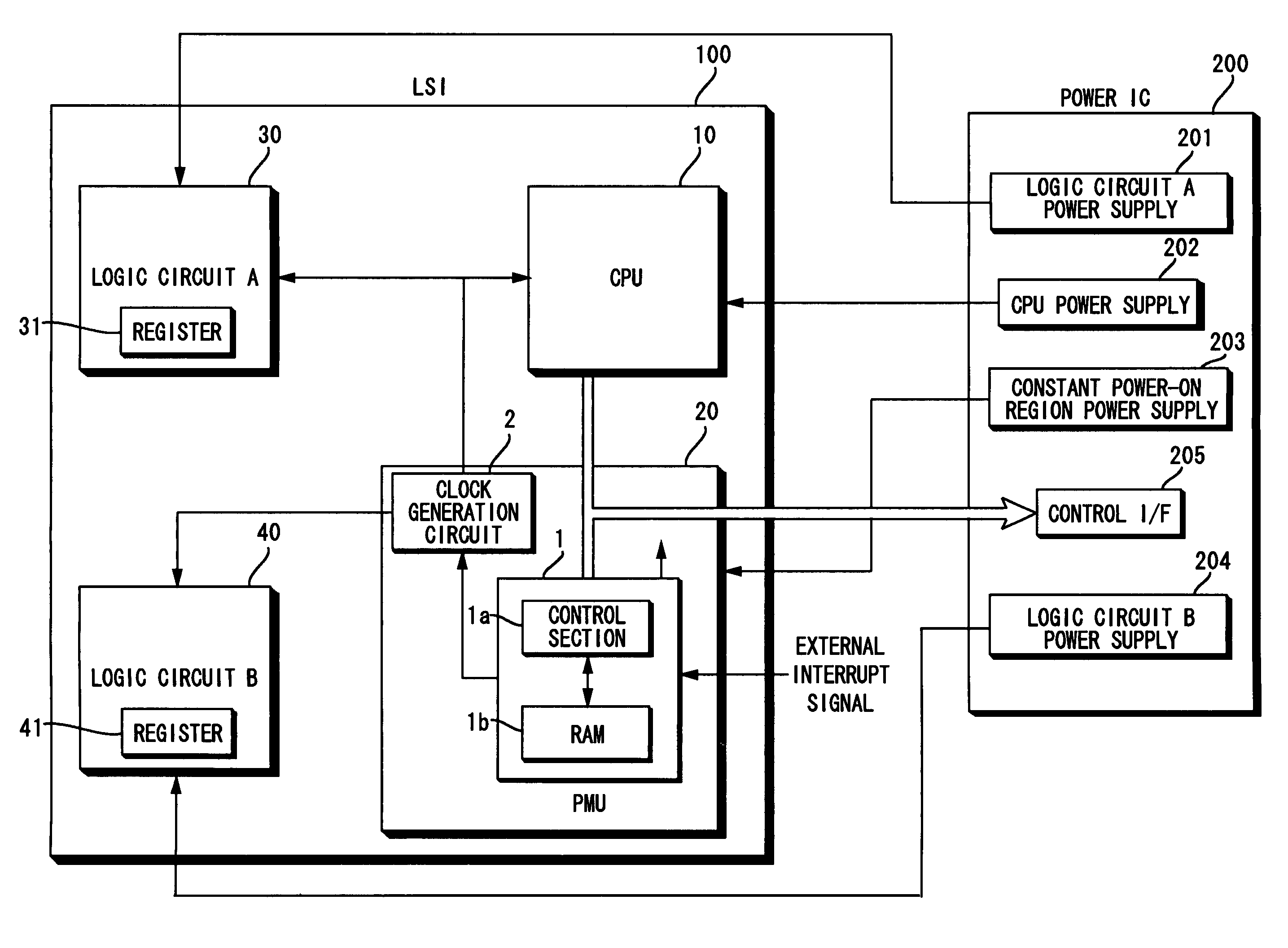
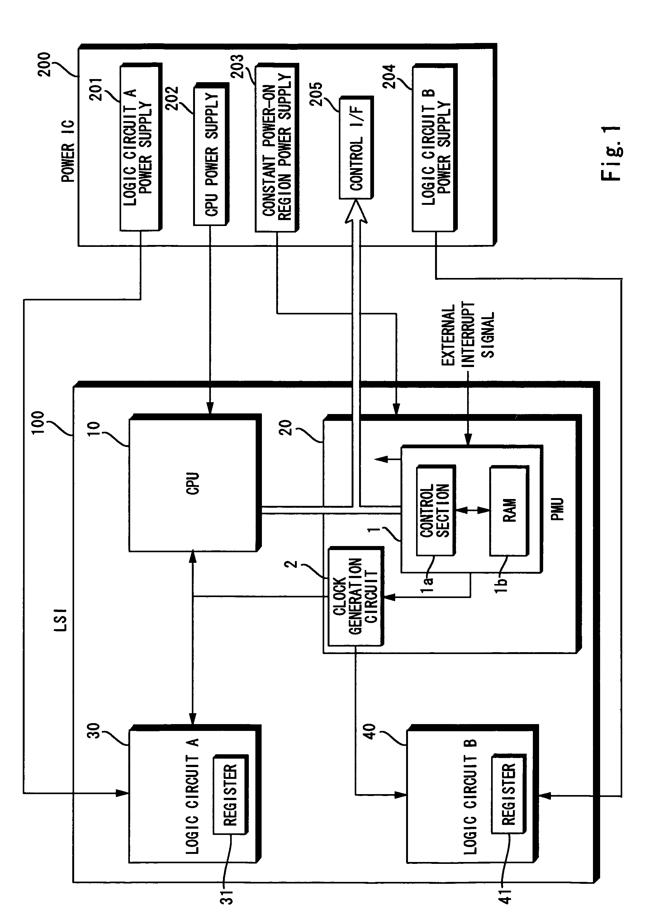
[0021]A power control technique according to a first embodiment of the invention is described hereinafter with reference to FIG. 1. As shown in FIG. 1, the integrated circuit device of this invention has a LSI 100 and a power IC 200, and it is incorporated in a mobile phone, for example, as an application processor. The LSI 100 is connected to the power IC 200 that is placed separately from the LSI 100. The LSI 100 has a CPU 10, a constant power-on region 20, a logic circuit A 30, and a logic circuit B 40. The constant power-on region 20 has a power management unit (PMU) 1 and a clock generation circuit 2. The CPU 10 has an arithmetic circuit. The CPU 10 and the PMU 1 are connected by a common bus, and signals from the CPU 10 and the PMU 1 are selectively supplied to the power IC 200 through the bus. It is feasible to place a selector for switching signals from the CPU 10 and the PMU 1.

[0022]The PMU 1 has functions to control power supply to the CPU 10, the logic circuit A 30, the l...

second embodiment

[0050]A power control technique according to a second embodiment of the invention is described hereinafter with reference to FIG. 5. The second embodiment has power supply switches 3a, 3b, 3c, 3d and 3e that correspond to macros placed inside the LSI 100, and the PMU 1 controls on / off of the power switches 3a to 3e.

[0051]Specifically, the power switches 3a to 3e are placed on branch lines that diverge from a line through which power is supplied constantly from the power IC 200 and are connected to each of the CPU 10 and logic circuits A 30, B 40, C 50 and D 60. Power is supplied from a LSI power supply section 207 of the power IC 200 to the CPU 10 through the power switch 3a. Similarly, power is supplied to the logic circuit A 30 through the power switch 3b, to the logic circuit B 40 through the power switch 3c, to the logic circuit C 50 through the power switch 3d, and to the logic circuit D 60 through the power switch 3e. The power switches 3a, 3b, 3c, 3d and 3e are placed in the...


PUM


Abstract

The integrated circuit device includes a CPU having an arithmetic circuit and a Power Management Unit implementing power control of the CPU through a power IC. The Power Management Unit has no arithmetic circuit. The Power Management Unit includes RAM storing a plurality of commands and a control section implementing power control of the CPU according to the commands stored in the RAM.

Description

BACKGROUND OF THE INVENTION[0001]1. Field of the Invention[0002]The present invention relates to an integrated circuit device and, particularly, to power control of an integrated circuit.[0003]2. Description of Related Art[0004]Various types of large scale integrations (LSI) are incorporated in mobile phones and mobile terminals that are driven by a battery. Reduction of power consumption in LSI is very important factor to enable long time use and achieve multifunction of mobile phones and so on. Further, as LSI becomes more complex, the proportion of static consumption current or leakage current that is consumed in stop state to entire consumption current rises so high that it is not negligible in a microfabrication process of 0.13 μm or less.[0005]In order to reduce leakage current, there is proposed a technique that divides the inside of LSI into a plurality of blocks and supplies power individually to each block, thereby stopping power supply to the block that is not necessary f...

Claims


Application Information

Patent Timeline
Patent Type & Authority Patents(United States)
IPC IPC(8): G06F1/00
CPCG06F1/3203G06F1/26
Inventor TOKUE, TATSUYA
Owner RENESAS ELECTRONICS CORP
Why Eureka
Try Eureka