Actuator provided with wave reduction gear

a wave reduction gear and actuator technology, applied in the direction of gearing, dynamo-electric machines, dynamo-electric components, etc., can solve the problem that the configuration in which the wave reduction gear, the motor and the position detector are coaxially arranged along the axial direction of the actuator is unsuitable for flattering the actuator, and achieves the effect of reducing the axial length of the actuator and reducing the effect of electromagnetic nois

Active Publication Date: 2010-07-13
HARMONIC DRIVE SYST IND CO LTD
View PDF7 Cites 14 Cited by
  • Summary
  • Abstract
  • Description
  • Claims
  • Application Information

AI Technical Summary

Benefits of technology

[0017]When wiring brought out from the magnetic sensor is brought out from the wave reduction gear to the exterior and is then brought around to the rear side of the motor, the wiring thus brought out is susceptible to mechanical damage when the actuator is installed and at other times. The detection signals outputted from a Hall element or other magnetic sensor are relatively weak electrical signals, and are therefore adversely affected when the signal wires are brought out because the signals are easily affected by electromagnetic noise. In the present invention, the wiring is not required to be brought out to the exterior, indirectly routed along the exterior of the motor, and brought around to the rear side thereof Therefore, the wiring is not susceptible to mechanical damage and can be brought out with the shortest possible wiring distance, so the effect of electromagnetic noise can be reduced.
[0028]With the present invention, detection signals from the magnetic sensor of the angle detector are transmitted via wiring that has been brought out through wiring holes formed inside the motor to the sensor signal converter disposed on the rear end side of the motor in an actuator having a configuration in which the angle detector of the position detector is incorporated inside the wave reduction gear. Therefore, the wiring is not required to be brought out to the exterior, indirectly routed along the exterior of the motor, and brought out to the rear side thereof Therefore, the wiring is not mechanically damaged and can be brought out with the shortest possible wiring distance, so the effect of electromagnetic noise can also be reduced.

Problems solved by technology

However, the configuration in which the wave reduction gear, motor, and position detector are coaxially arranged along the axial direction of the actuator is unsuitable for making the actuator flatter.

Method used


Image

  • Actuator provided with wave reduction gear
  • Actuator provided with wave reduction gear
  • Actuator provided with wave reduction gear

Examples


Embodiment Construction

[0035]An embodiment of the actuator provided with a wave reduction gear in which the present invention has been applied will be described below with reference to the diagrams.

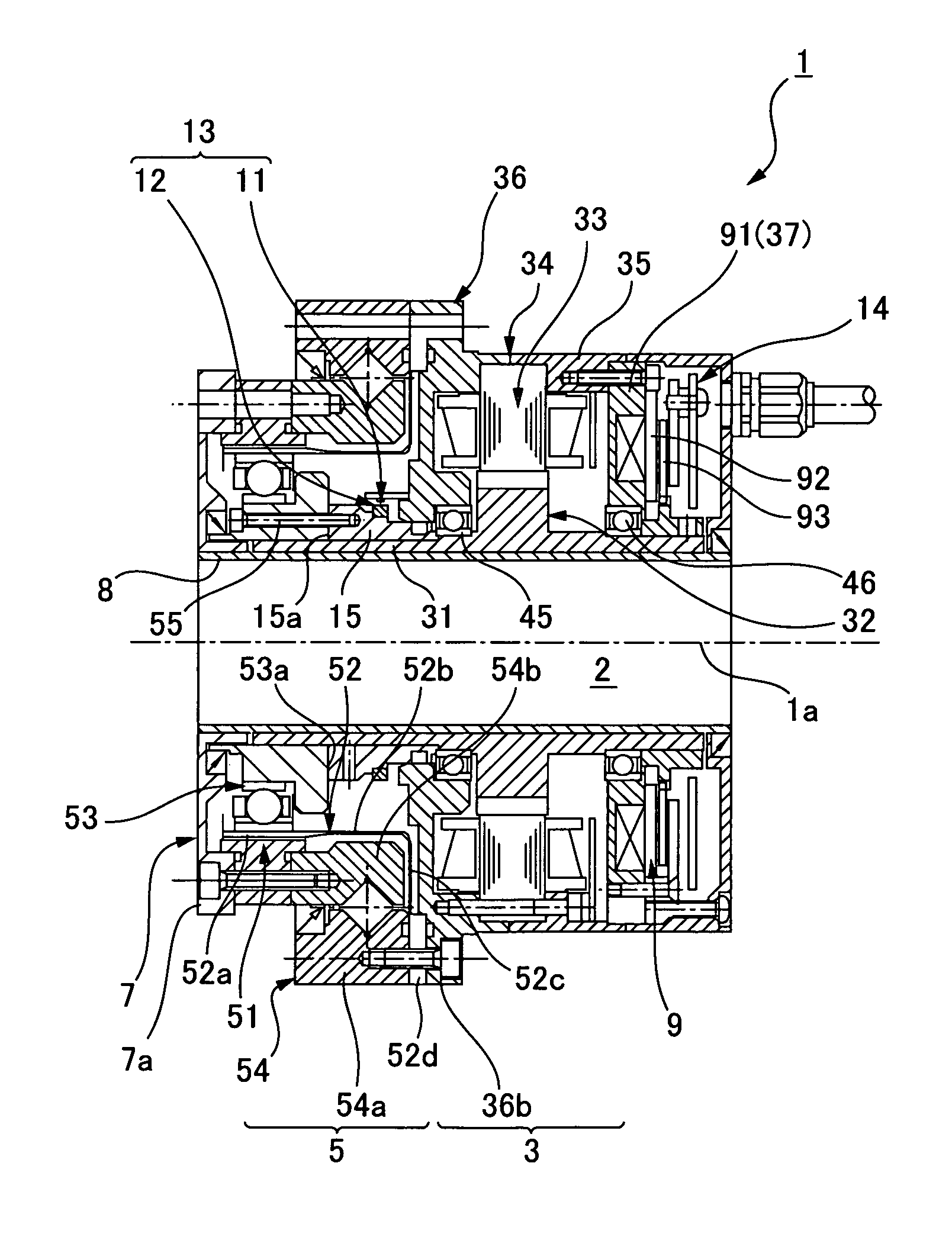
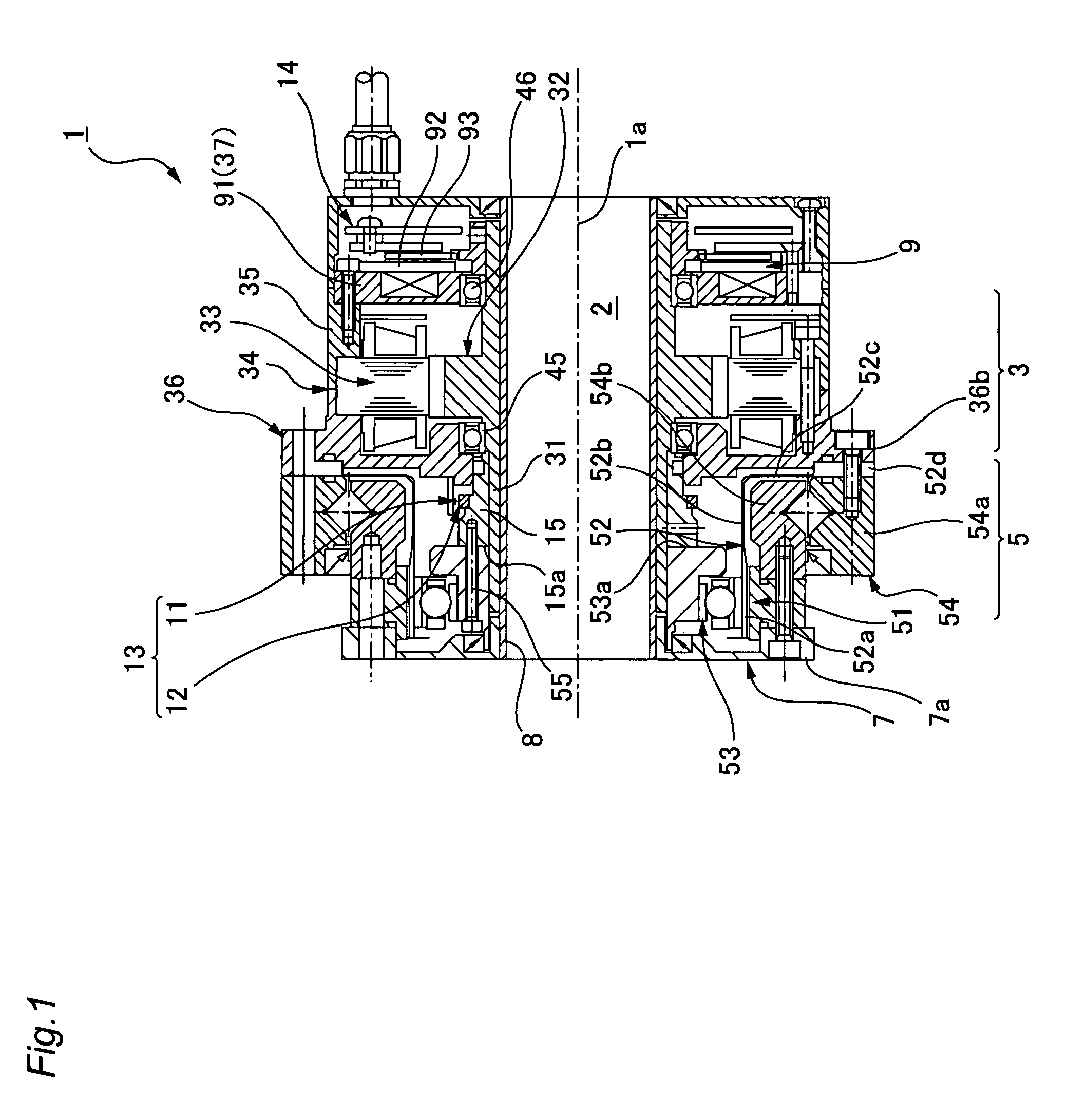
[0036]FIG. 1 is a longitudinal sectional view showing an actuator provided with a wave reduction gear according to the present invention. The actuator 1 is a hollow actuator in which a circularly cross-sectioned hollow portion 2 passes through the center thereof in the direction of the axis line 1a, and has a motor 3, a wave reduction gear 5 coaxially disposed on the front side thereof, and a discoid output shaft 7 coaxially disposed on the front side thereof The output shaft 7 is coaxially fixed to the external peripheral surface portion of the front end side of a hollow shaft 8 that defines the hollow portion 2. Also, an electromagnetic brake 9 is disposed on the rear side of the motor 3.

[0037]The motor 3 is provided with a hollow rotating shaft 31, a motor rotor 32 integrally formed with the rotating shaft 3...


PUM


Abstract

In an actuator (1) in which an angle detector (13) of a magnetic encoder for detecting the rotational position of a motor (3) is incorporated inside a wave reduction gear (5), detection signals from Hall elements (11a, 11b) of the angle detector (13) are transmitted via sensor lead wires (17) that have been brought out through wiring holes (36a, 33a, 35a, 37a) formed inside the motor (3) to a sensor signal converter board (14) disposed on the rear end side of the motor. Since the wiring is not required to be brought out to the exterior, indirectly routed along the exterior of the motor (3), and brought out to the rear side thereof, the wiring is not mechanically damaged and can be brought out with the shortest possible wiring distance, and the effect of electromagnetic noise can be reduced.

Description

TECHNICAL FIELD[0001]The present invention relates to a short actuator in which a wave reduction gear is housed.BACKGROUND ART[0002]A wave reduction gear is composed of an annular rigid internal gear, a flexible external gear disposed therein, and a wave generator which flexes the flexible external gear in the radial direction to mesh with the rigid internal gear and causes to move the meshing position of the gears in the circumferential direction. In an actuator composed of a motor and this wave reduction gear, the rotating shaft of the motor is coaxially connected to the wave generator, and considerably reduced rotations are outputted from the rigid internal gear or the flexible external gear in accordance with the difference in the number of teeth between the two gears.[0003]With an actuator thusly configured, the wave reduction gear is coaxially disposed at the distal end of the motor, and a magnetic position detector is mounted on the rear end portion of the rotating shaft of t...

Claims


Application Information

Patent Timeline
Patent Type & Authority Patents(United States)
IPC IPC(8): F16H33/00
CPCH02K7/116H02K11/0021Y10T74/19H02K11/215
Inventor MARUYAMA, TOSHIKIKOJIMA, TAKAYUKI
Owner HARMONIC DRIVE SYST IND CO LTD
Why Eureka
Try Eureka