Power supply monitoring for an implantable device

a technology of power supply monitoring and implantable devices, which is applied in electrotherapy, therapy, heart stimulators, etc., can solve the problems of inability to accurately and unambiguously determine the current status of the battery from the measured battery characteristic, and the discharge of the rechargeable battery eventually may need replacement, etc., to achieve accurate and unambiguous calculation

Inactive Publication Date: 2007-08-02
LIVANOVA USA INC
View PDF5 Cites 7 Cited by
  • Summary
  • Abstract
  • Description
  • Claims
  • Application Information

AI Technical Summary

Benefits of technology

[0015]In still another embodiment, extreme temperatures may adversely affect the calculation of time remaining. Therefore, the measured Voltage may be compensated for temperature according to the following equation: Vcompensated=Vmeasurement+(K×(Tbaseline−Tmeasurement)); and the time remaining may be more accurately calculated using the Vcompensated value as the battery voltage.

Problems solved by technology

Even rechargeable batteries eventually may need replacement.
One problem associated with these methodologies is that, for many battery chemistries, these measured battery characteristics do not have monotonically-changing values with respect to remaining charge.
For example, lithium / carbon monofluoride (Li / CFx) cells commonly used in neurostimulators and other IMDs have a relatively flat voltage discharge curve for the majority of their charge life, and present status of the battery cannot be accurately and unambiguously determined from a measured battery characteristic.
Another problem associated with impedance-based methodologies is the variability of current consumption for a specific device's programmed therapy or circuitry.
This variability, combined with the uncertainty of the battery's present status prior to depletion, hinders reliable estimation of the anticipated time until reaching the end of the battery's useful life.

Method used


Image

  • Power supply monitoring for an implantable device
  • Power supply monitoring for an implantable device
  • Power supply monitoring for an implantable device

Examples


Embodiment Construction

[0034]Illustrative embodiments of the disclosure are described herein. In the interest of clarity, not all features of an actual implementation are described in this specification. In the development of any such actual embodiment, numerous implementation-specific decisions must be made to achieve the design-specific goals, which will vary from one implementation to another. It will be appreciated that such a development effort, while possibly complex and time-consuming, would nevertheless be a routine undertaking for persons of ordinary skill in the art having the benefit of this disclosure.

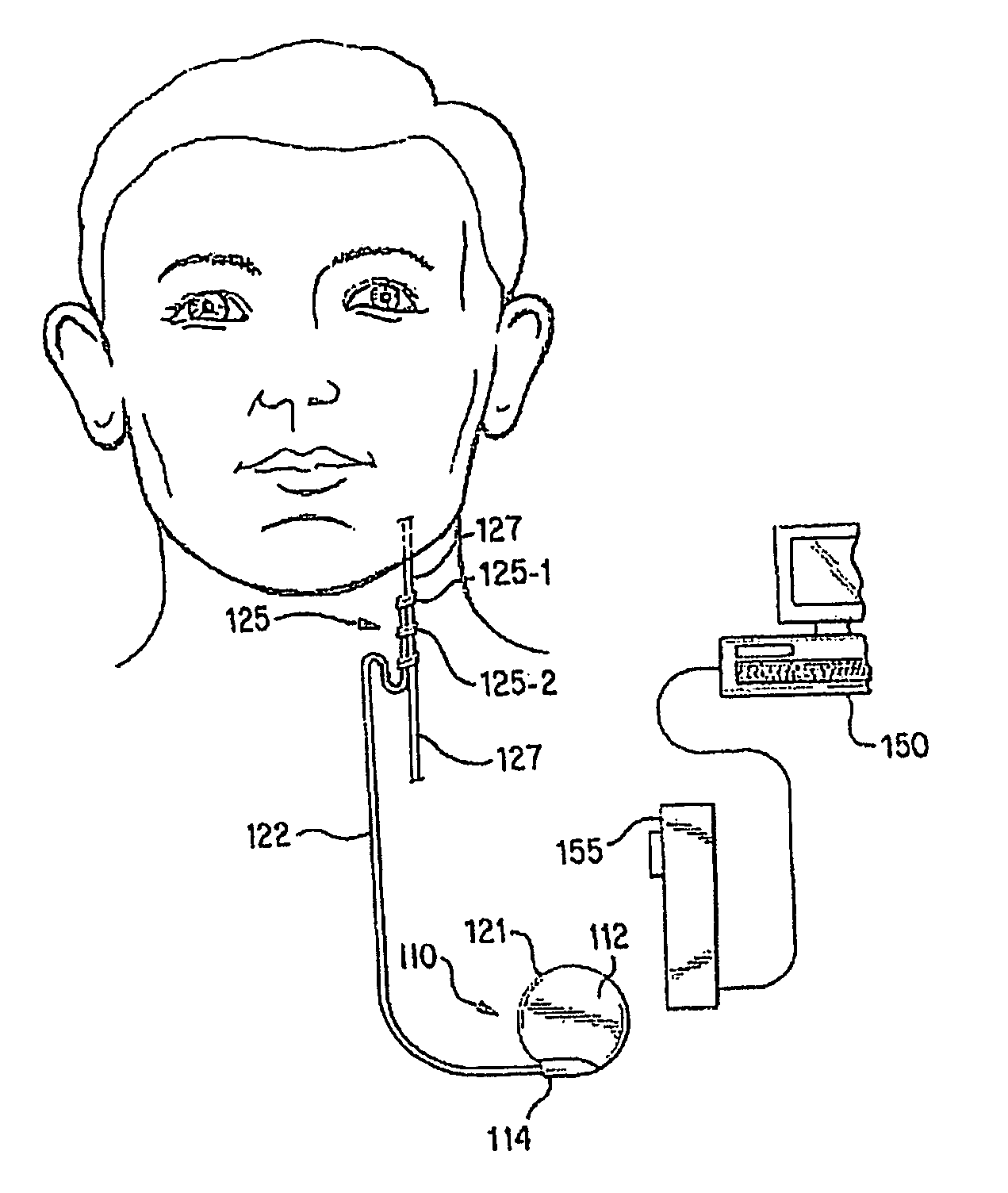
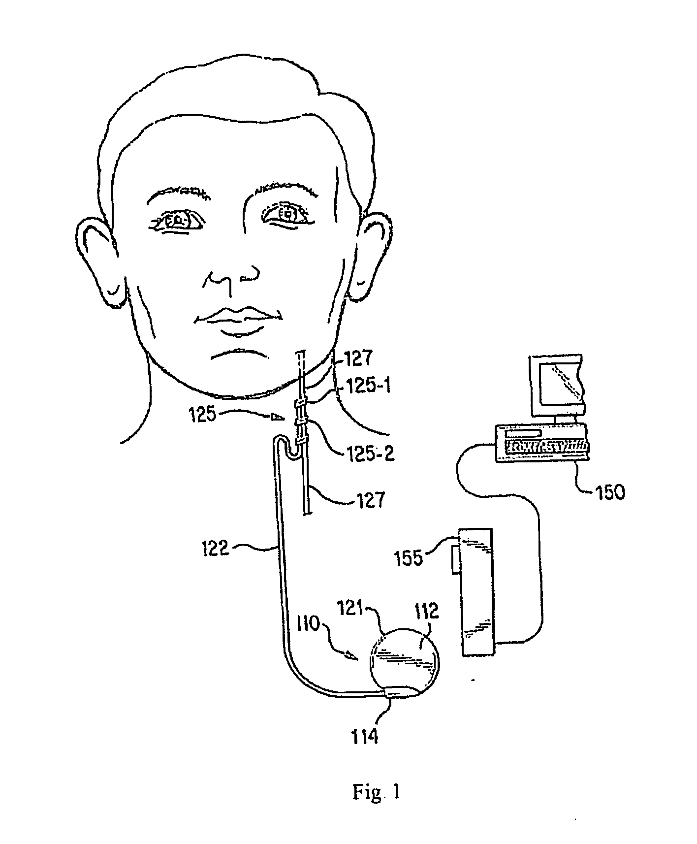
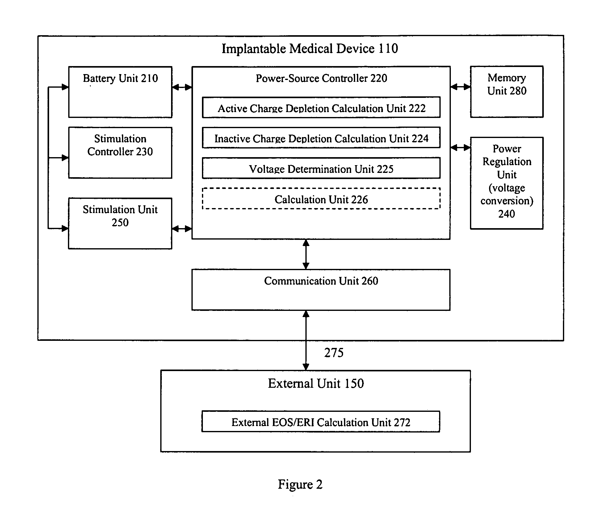
[0035]Embodiments of the present disclosure provide methods and apparatus for monitoring and / or estimating the time remaining until the generation of an elective replacement indicator or until the end of service of the battery of an implantable medical device (IMD). Estimating battery life may be based upon 1) estimated future charge depletion and actual past charge depletion while the battery is...


PUM


Abstract

A method and an apparatus for determining a time period remaining in a useful life of an energy storage device in an implantable medical device. The method may include measuring a voltage of the energy storage device to produce a measured voltage, and comparing the measured voltage to a transition voltage. While the measured voltage is greater than or equal to the transition voltage, the time period remaining in the energy storage device's useful life is approximated based upon a function of charge depleted. While the measured voltage is less than the transition voltage, the time period remaining in the energy storage device's useful life is approximated based upon a higher order polynomial function of the measured voltage. The transition voltage corresponds to a predetermined point on a energy storage device voltage depletion curve representing the voltage across the energy storage device over time.

Description

CROSS-REFERENCE TO RELATED APPLICATIONS[0001]This application claims priority to U.S. patent application Ser. No. 11 / 341,978, filed on Jan. 27, 2006, and entitled “Improved Power Supply Monitoring For An Implantable Device.” This reference is incorporated herein by reference.BACKGROUND[0002]1. Technical Field[0003]This disclosure relates generally to implantable medical devices, and more particularly to monitoring power consumption.[0004]2. Background Information[0005]There have been many improvements over the last several decades in medical treatments for disorders of the nervous system, such as epilepsy and other motor disorders, and abnormal neural discharge disorders. One of the more recently available treatments involves the application of an electrical signal to reduce various symptoms or effects caused by such neural disorders. For example, electrical signals have been successfully applied at strategic locations in the human body to provide various benefits, including reducin...

Claims


Application Information

Patent Timeline
Patent Type & Authority Applications(United States)
IPC IPC(8): A61N1/00
CPCA61N1/08A61N1/378A61N1/3708
Inventor ARMSTRONG, RANDOLPH K.ARMSTRONG, SCOTT A.INMAN, D. MICHAELSCOTT, TIMOTHY L.
Owner LIVANOVA USA INC
Why Eureka
Try Eureka