Compound cycle rotary engine

a rotary engine and compound cycle technology, applied in the direction of combustion engines, rotary or oscillating piston engines, machines/engines, etc., can solve the problems of limiting the engine's ability to operate at high speed, high power to weight, and exceeding 2.0 hp/lbm, etc., to achieve low specific fuel consumption and high power to weight

Active Publication Date: 2010-07-13
RTX CORP
View PDF33 Cites 189 Cited by
  • Summary
  • Abstract
  • Description
  • Claims
  • Application Information

AI Technical Summary

Benefits of technology

[0008]There is provided a compound cycle engine system which is capable of achieving low specific fuel consumption at relatively high power to weight. The compound cycle engine system broadly comprises a rotary engine, which rotary engine generates an exhaust gas, means for supplying inlet air at a pressure in the range of from 3.0 to 5.0 atmospheres and a temperature in the range of from 150 to 250 degrees Fahrenheit to the rotary engine, and means for extracting energy from the exhaust gas from the rotary engine.

Problems solved by technology

Gas turbine engines in the 500 to 3000 shaft horsepower range are well known for having very high power to weight (power produced per unit weight), but at high specific fuel consumption (fuel flow rate per unit power, SFC).
While these engines have been successful in achieving low SFCs (around 0.33 lbm / hr / hp), they have not achieved high power to weight (exceeding 2.0 hp / lbm).
This is due primarily to the reciprocating masses (pistons), valves and combustion systems inherent in a CI engine that limits the engine's ability to operate at high speed.
Also, the chamber pressures and temperatures at which CI engines operate require heavy structures for containment.

Method used


Image

  • Compound cycle rotary engine
  • Compound cycle rotary engine
  • Compound cycle rotary engine

Examples


Embodiment Construction

)

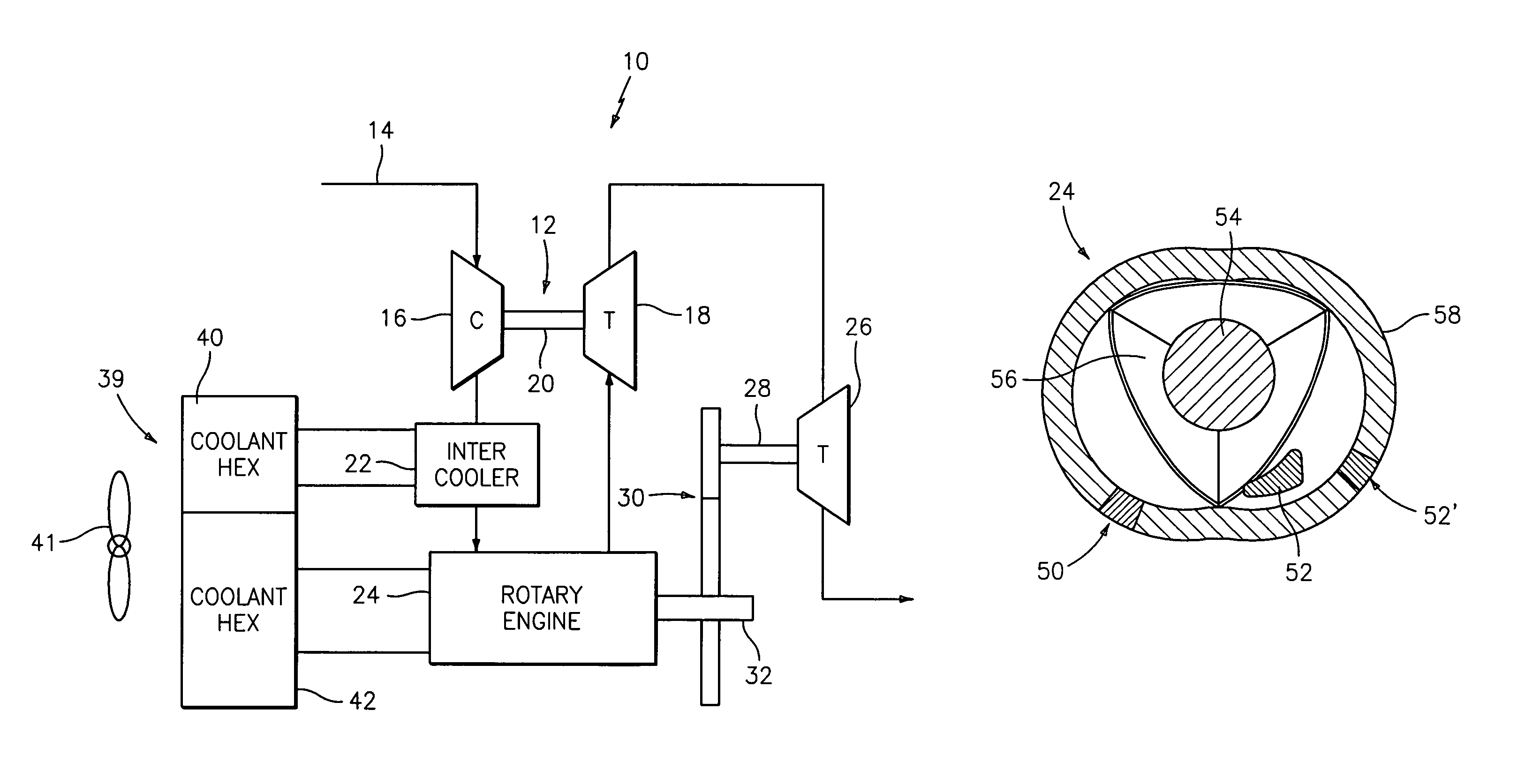
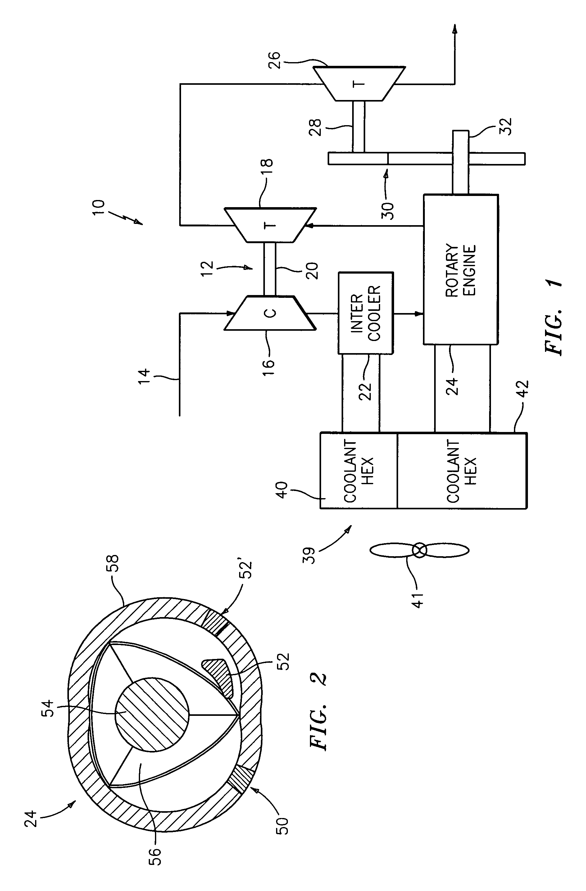
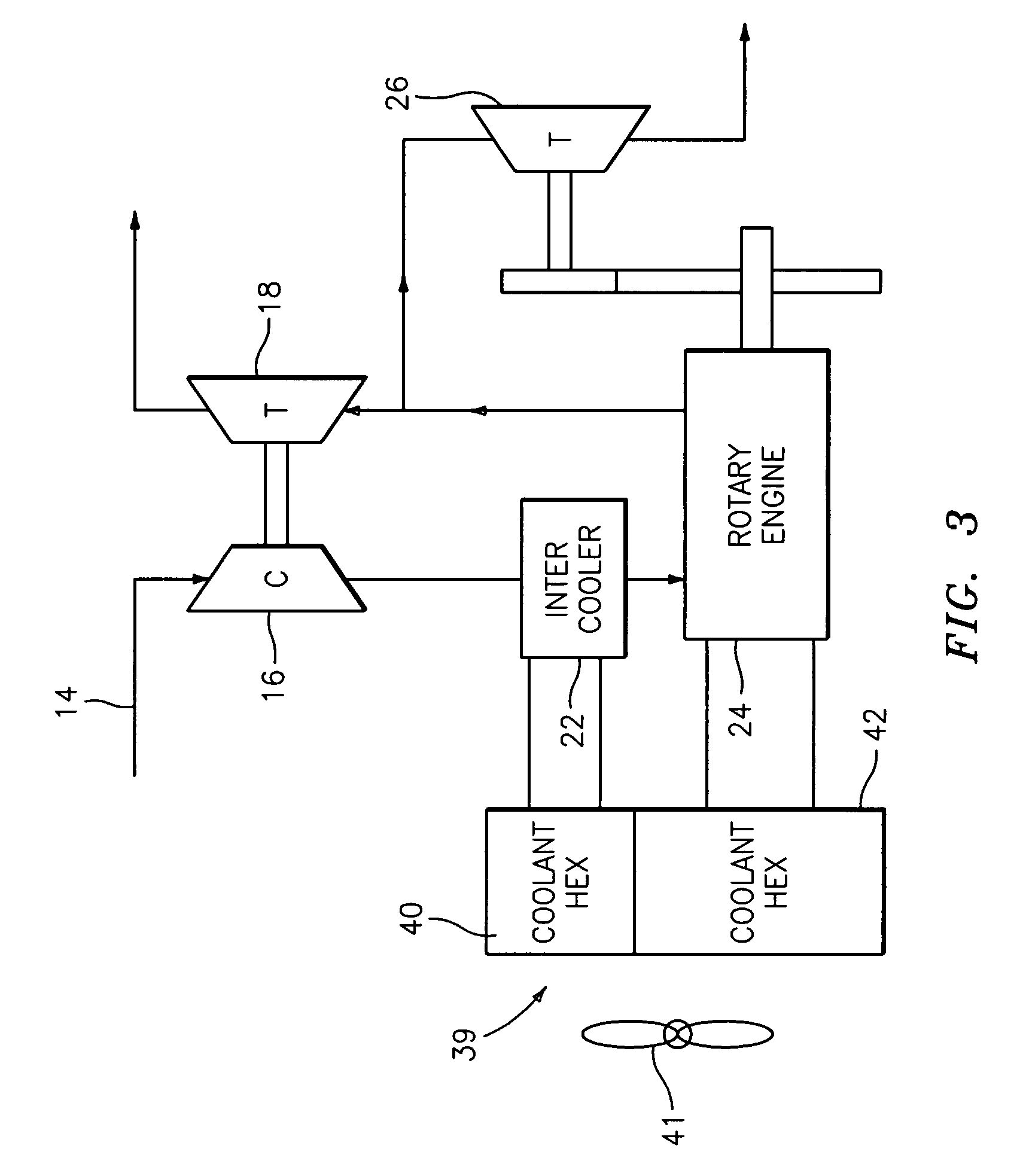
[0013]Referring now to FIG. 1, there is shown a compound engine cycle 10 which includes a turbocharger 12 that receives air from an inlet 14. The turbocharger 12 includes a compressor 16 and a turbine 18 which are connected by a shaft 20. The compressor 16 may be a single- or multiple-stage centrifugal device and / or an axial device. The air from the inlet 14 flows into the compressor 16. The compressor 16 preferably increases the pressure of the air flow to a level in the range of from 3.0 to 5.0 atmospheres.

[0014]The air exiting the compressor 16 flows into an intercooler 22 where the temperature of the air is lowered to a relatively low level, i.e. the air exiting the intercooler 22 and entering the inlet of a rotary engine 24 is in the range of from 150 to 250 degrees Fahrenheit. As a result of passing the inlet air through the compressor 16 and the intercooler 22, a very high density inlet air can be supplied to the inlet of the rotary engine 24. A rotary engine 24 with such hi...


PUM


Abstract

A compound cycle engine system has a rotary engine, which rotary engine generates exhaust gas. The system further has a compressor for increasing the pressure of inlet air to be supplied to the engine to a pressure in the range of from 3.0 to 5.0 atmospheres and an intercooler for providing the inlet air to the engine at a temperature in the range of from 150 to 250 degrees Fahrenheit. The system further has one or more turbines for extracting energy from the exhaust gas. The Miller Cycle is implemented in the rotary engine, enabling the compression ratio to be lower than the expansion ratio, allowing the overall cycle to be optimized for lowest weight and specific fuel consumption.

Description

BACKGROUND[0001](1) Field of the Invention[0002]The present disclosure relates to a compound cycle rotary engine that offers low specific fuel consumption at high power to weight. The compound cycle rotary engine has particular utility for propulsion systems.[0003](2) Prior Art[0004]Gas turbine engines in the 500 to 3000 shaft horsepower range are well known for having very high power to weight (power produced per unit weight), but at high specific fuel consumption (fuel flow rate per unit power, SFC). Intermittent combustion engines (e.g. spark ignition, or SI, reciprocating engines and compression ignition, or CI, reciprocating engines) are well known for having low SFC, but at low power to weight. It is desirable to achieve low SFC at high power to weight. A compound engine cycle which combines certain features of both engine types has the potential to achieve low specific fuel consumption at relatively high power to weight.[0005]Compound engine cycles are well documented in the ...

Claims


Application Information

Patent Timeline
Patent Type & Authority Patents(United States)
IPC IPC(8): F02B33/00
CPCF01C1/22F01C11/008F02B37/00F02B41/10F02B53/04F02B29/0437F02B2275/32Y02T10/144Y02T10/142Y02T10/163Y02T10/17Y02T10/12
Inventor LENTS, CHARLES E.ZEPPIERI, STEPHEN P.GUILE, ROY N.NARDONE, VINCENT C.LAUTER, JONATHANDASGUPTA, ARINDAM
Owner RTX CORP
Why Eureka
Try Eureka