CT gantry mounted radioactive source loader for PET calibration

a radioactive source and loader technology, applied in the field of diagnostic imaging, can solve the problems of affecting the operation of the system, occupying a considerable amount of space, and the inability to mount the source pin directly to the rotatable transmission ring, and a greater chance of mechanical or electrical failure in the system

Inactive Publication Date: 2010-07-13
GENERAL ELECTRIC CO
View PDF9 Cites 38 Cited by
  • Summary
  • Abstract
  • Description
  • Claims
  • Application Information

AI Technical Summary

Problems solved by technology

Because the pins are radioactive, they are stored in a shielded storage device when not in use.
The shielded storage device in existing systems is rather large and takes up a considerable amount of space due in part to the fact that the source pin is a rigid member.
However, because of the large size of the storage device, it is not possible to mount the source pin directly to the rotatable transmission ring.
In addition to unwanted radiation exposure, the transport of the source pin from the storage device to the rotation ring also creates a greater opportunity for mechanical or electrical failure to occur in the system.
That is, the transition of the radioactive source pin from the storage shield to its mounting on the rotatable transmission ring involves a number of motion steps in which problems can arise.
Because the shielding requirements limit the placement of the storage device, the automatic source pin handling and these motion steps are often complex and unreliable.

Method used


Image

  • CT gantry mounted radioactive source loader for PET calibration
  • CT gantry mounted radioactive source loader for PET calibration
  • CT gantry mounted radioactive source loader for PET calibration

Examples


Embodiment Construction

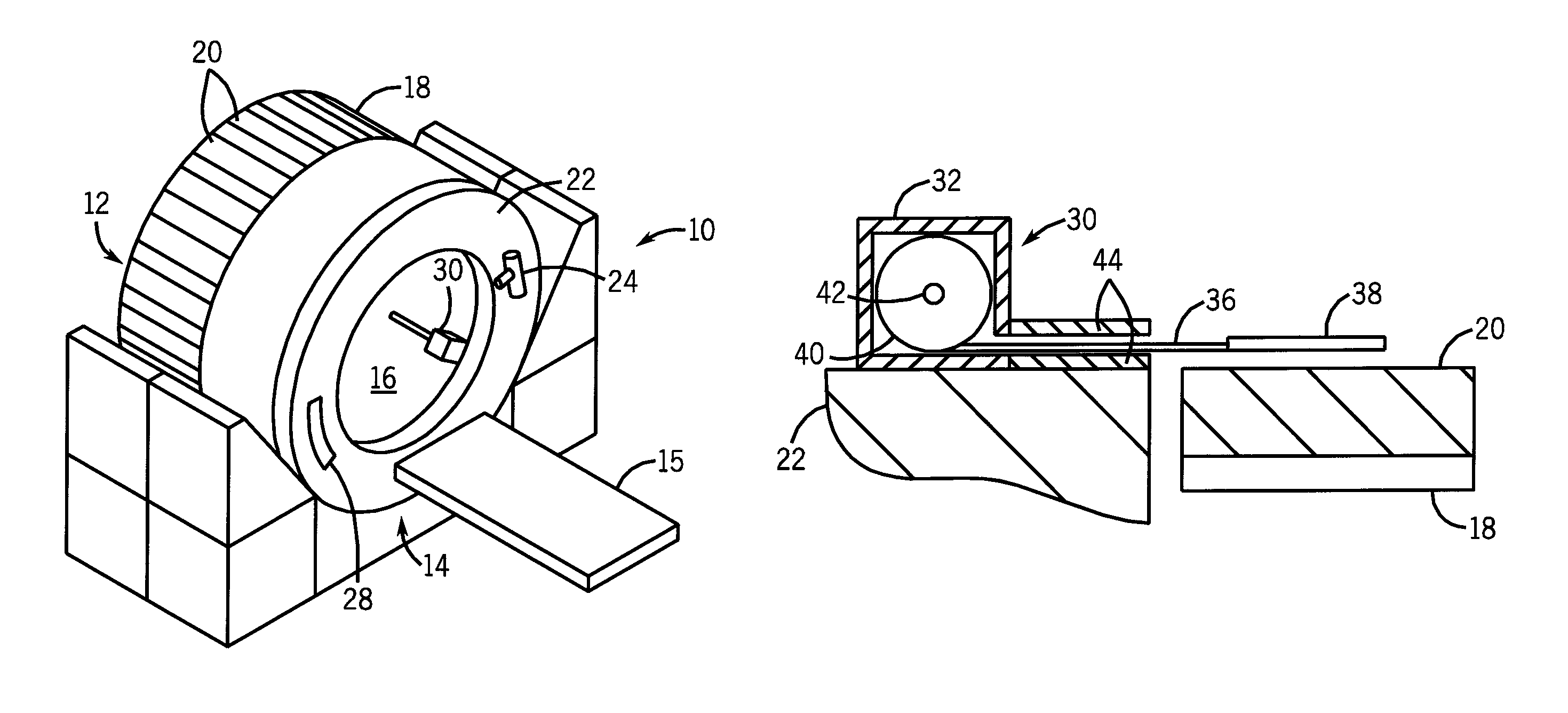
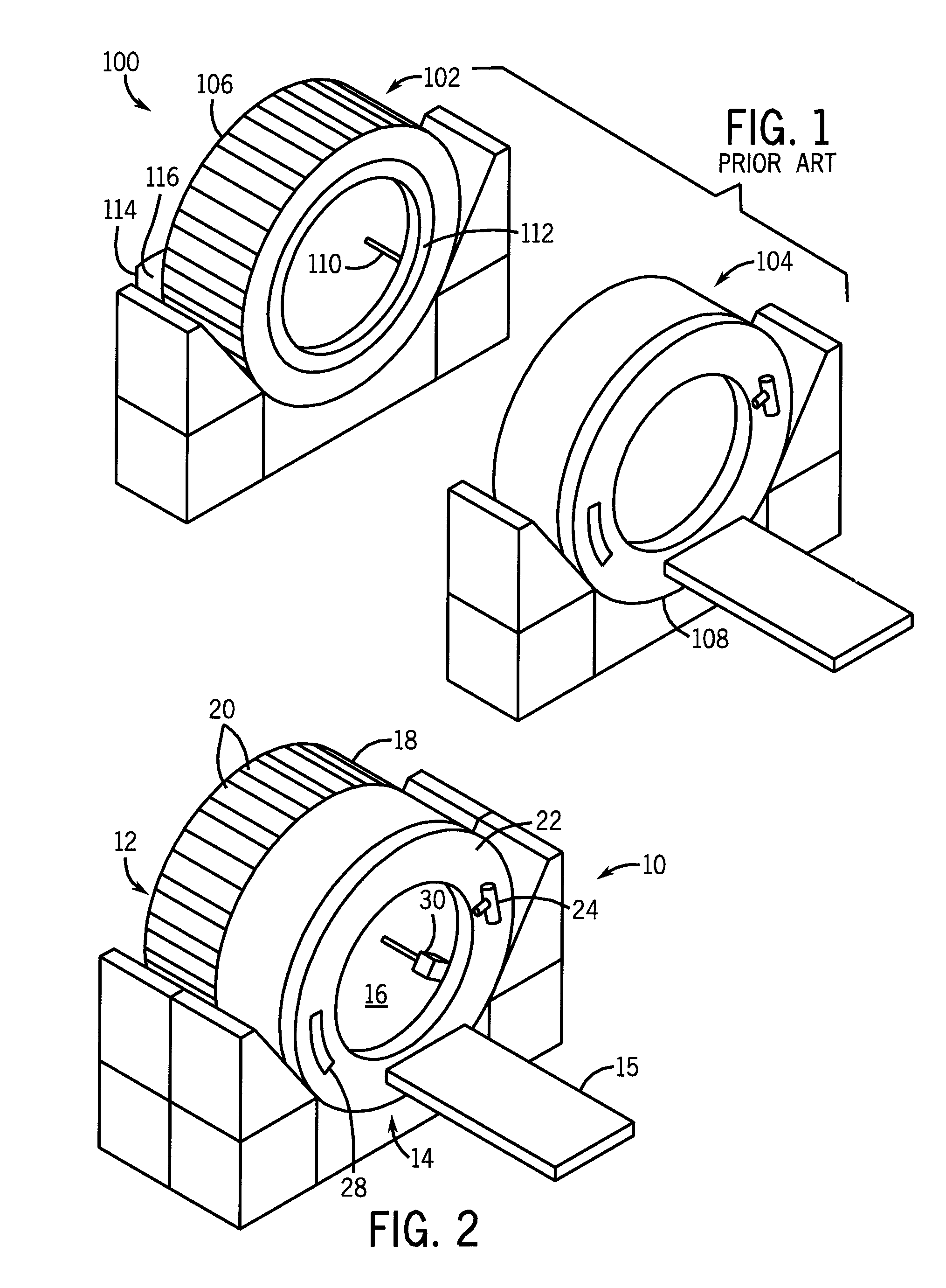
[0020]Referring to FIG. 1, a combination PET / CT imaging system 100 as known in the prior art is shown. The PET / CT system 100 is constructed to include a PET system 102 and CT system 104 mounted on separate gantries 106, 108. Before scanning of a patient takes place in the system, calibration of the PET system 102 is necessary to ensure accurate readings by the PET detectors therein. In order to calibrate the PET system 102, a radioactive source 110 must be rotated about the PET gantry 106. However, the PET gantry 106 is not capable of rotation, and as such, the rotation of this radiation source 110 in the prior art PET / CT system 100 is achieved by way of a rotation ring 112. During a calibration process the radiation source 110 is placed in the rotation ring 112, which is configured as a separate structure that is mounted to the PET gantry 106 to allow for rotation of the radiation source 110.

[0021]Because the radiation emitted by the radiation source 110 is not desirable outside of...


PUM


Abstract

A medical imaging system is provided including a positron emission tomography (PET) imaging apparatus and a computed tomography (CT) imaging apparatus. The CT imaging apparatus includes a rotatable gantry. A radioactive source loader is attached to the rotatable gantry to rotate therewith. The radioactive source loader further includes a radioactive source to calibrate the PET imaging apparatus.

Description

BACKGROUND OF THE INVENTION[0001]The present invention relates generally to apparatus used in diagnostic imaging and, more particularly, to a method and apparatus for loading and storing radioactive source pins used in combination PET / CT imaging systems.[0002]The combination PET / CT system has been recognized as an effective medical imaging system that can improve patient diagnosis by producing high quality medical images that not only provide anatomical information and images, but also provides physiological information on the patient.[0003]In the combination PET / CT system, radioactive source pins are used to calibrate the PET detector system and to provide attenuation correction during system use or imaging. Because the pins are radioactive, they are stored in a shielded storage device when not in use. The storage device is structurally secure and shields the environment from radiation exposure from the radioactive source pin. Typically, the storage devices and source pins (i.e., s...

Claims


Application Information

Patent Timeline
Patent Type & Authority Patents(United States)
IPC IPC(8): H01L27/146G01T1/29G21F5/02G01T1/164
CPCG01T1/1611G01T1/1644
Inventor KIM, CHANG L.
Owner GENERAL ELECTRIC CO
Why Eureka
Try Eureka