Electrical domain compensation of non-linear effects in an optical communications system

a technology of nonlinear effects and optical communications, applied in electromagnetic transmission, electrical apparatus, transmission, etc., can solve the problems of limiting system performance and signal reach, increasing transmission power level, and optical signal degradation

Active Publication Date: 2010-07-13
CIENA
View PDF45 Cites 96 Cited by
  • Summary
  • Abstract
  • Description
  • Claims
  • Application Information

AI Technical Summary

Benefits of technology

[0017]An object of the present invention is to provide a method and apparatus for at least partiall

Problems solved by technology

However, conventional optical fibres comprise an optical transmission medium which exhibits nonlinear effects at high optical power levels, resulting in degradation of the optical signal.
These nonlinear effects are generally a function of optical power, and so any increase in transmission power level tends to increase signal degradations due to system nonlinearities.
Of particular concern in considering nonlinear processes are the effects of phase nonlinearities, which increase as data rates and optical power levels increase, and which ultimately limit both system performance and signal reach.
This finite bandwidth results in some optical signal power in one channel “leaking” through the filters of adjacent channels.
A limitation of this technique is that the pre-chirp is imposed as a discrete step prior to MUXing each channel into the optical fiber link 4.
Consequently, while this technique facilitates compensation of XPM and

Method used


Image

  • Electrical domain compensation of non-linear effects in an optical communications system
  • Electrical domain compensation of non-linear effects in an optical communications system
  • Electrical domain compensation of non-linear effects in an optical communications system

Examples


Embodiment Construction

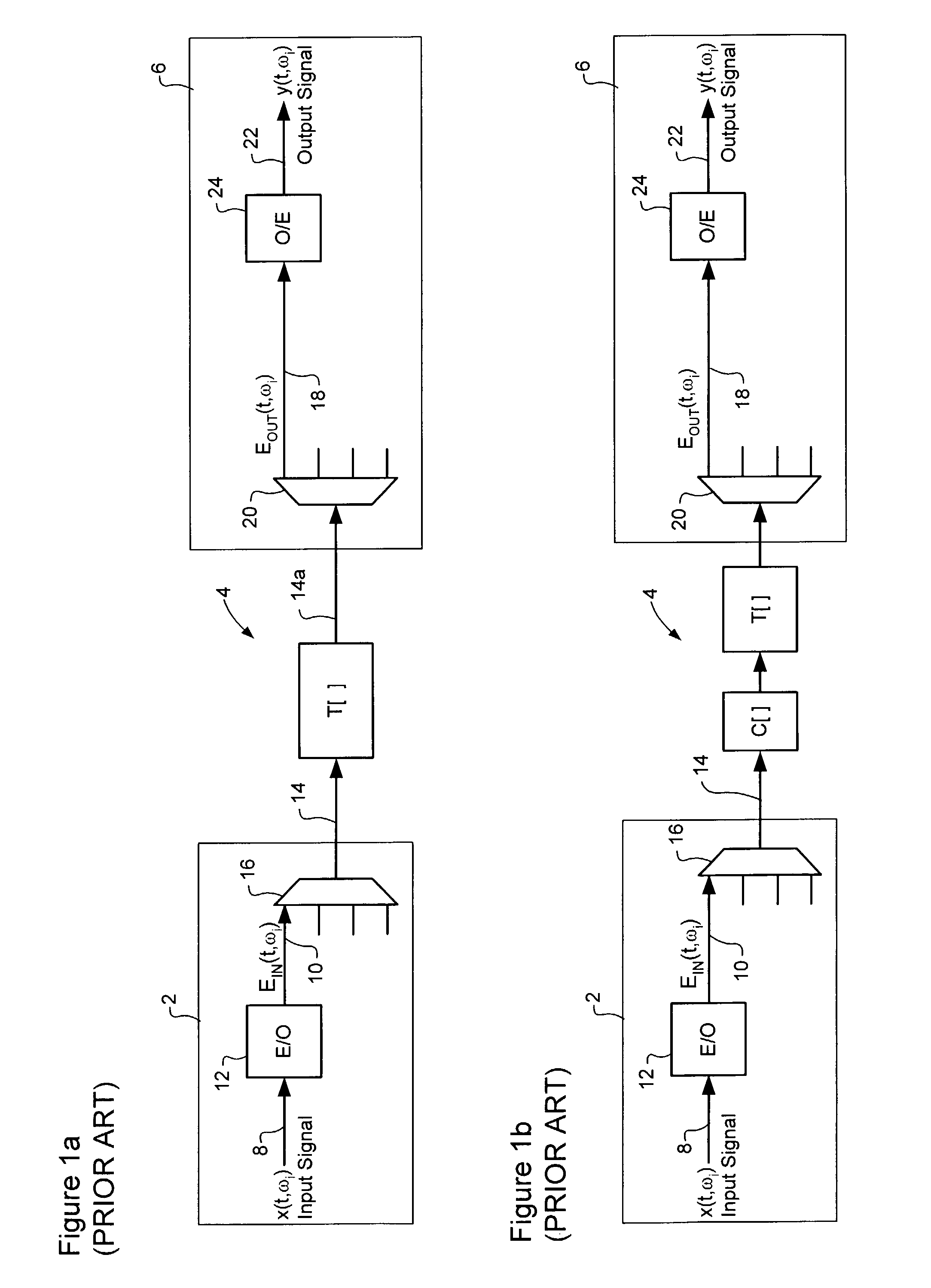
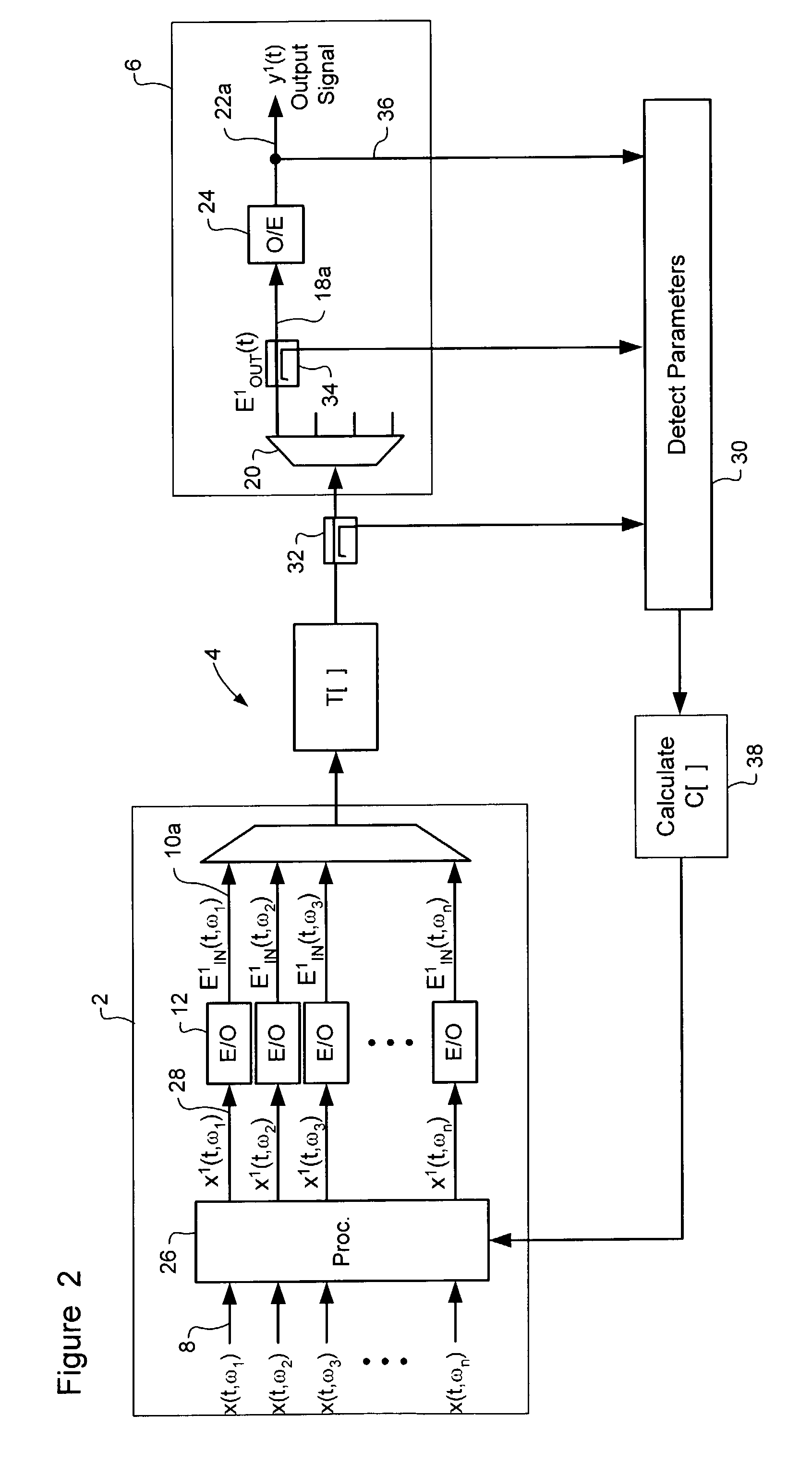
[0031]The present invention provides a method and system for compensation of non-linear and cross channel effects in an optical communications system. For the purposes of the present invention, “non-linear and cross-channel effects” shall be understood to refer to signal distortions due to phase non-linearities, such as Self Phase Modulation (SPM) cross-phase modulation (XPM), Modulation instability (MI) and four-wave mixing. “Cross-channel effects” shall be understood to refer to signal distortions due to optical cross-talk. FIG. 2 is a block diagram schematically illustrating principal elements and operations of a compensation system in accordance with the method of the present invention.

[0032]In accordance with the present invention, signal distortions due to the link complex non-linear operator T[E(t)] are at least partially compensated by deriving a compensation operator C[E(t)] that optimizes the performance of the link 4, and then predistorting the input signal x(t), in the e...


PUM


Abstract

Nonlinearity-induced signal distortions are compensated by processing an input communications signal, in the electrical domain prior to Electrical-to-optical conversion and transmission through an optical link of a communications system. According to the invention, a compensation operator is determined that substantially mitigates the nonlinearity-induced signal distortions imparted to an optical signal traversing the communications system. The input communications signal is then input to the compensation operator to generate a predistorted electrical signal. This predistorted electrical signal is then used to modulate an optical source to generate a corresponding predistorted optical signal for transmission through the optical communications system. With this arrangement, arbitrary nonlinearity-induced signal distortions imparted by the optical link can be compensated in such a manner that a comparatively undistorted optical signal is obtained at the receiving end of the optical link.

Description

CROSS-REFERENCE TO RELATED APPLICATIONS[0001]This application is a Continuation-in-Part of U.S. patent application Ser. No. 10 / 262,944 filed Oct. 3, 2002 now U.S. Pat. No. 7,382,984.MICROFICHE APPENDIX[0002]Not Applicable.TECHNICAL FIELD[0003]The present invention relates to optical communications systems, and in particular to electrical domain compensation of Four Wave Mixing, SPM, XPM and optical cross-talk in an optical communications system.BACKGROUND OF THE INVENTION[0004]Optical communications systems typically include a pair of network nodes connected by an optical waveguide (i.e., fiber) link. Within each network node, communications signals are converted into electrical signals for signal regeneration and / or routing, and converted into optical signals for transmission through an optical link to another node. The optical link between the network nodes is typically made up of multiple concatenated optical components, including one or more (and possibly 20 or more) optical fib...

Claims


Application Information

Patent Timeline
IPC IPC(8): H04B10/00H04B10/18
CPCH04B10/2543
Inventor ROBERTS, KIM B.STRAWCZYNSKI, LEOO'SULLIVAN, MAURICE S.
Owner CIENA
Why Eureka
Try Eureka