Lubricant management method for a vehicle

Active Publication Date: 2010-07-13
GE GLOBAL SOURCING LLC
View PDF12 Cites 10 Cited by
  • Summary
  • Abstract
  • Description
  • Claims
  • Application Information

AI Technical Summary

Benefits of technology

[0007]A method for maintaining the quality of lubricant in the engine of a mobile vehicle is described herein as including: planning operation of a mobile vehicle for a number of operating periods separated by a respective number of maintenance periods; removing a test portion of lubricant from an engine of the mobile vehicle during a first of the maintenance periods; determining at least one quality parameter associated with the test portion of lubricant; using the at least one quality parameter to determine a replacement quantity of lubricant that must be removed from the engine and replaced with fresh lubricant in order to maintain a desired engine lubricant quality parameter in the engine until a second of the maintenance periods; and removing the replacement quantity of lubricant from the engine and replacing it with fresh lubricant. The method may further include: removing

Problems solved by technology

It is well known that the desirable properties of such fluids will degrade with continued operation of the engine, due to chemical changes in the fluid itself as well as the accumulation of contaminants that cannot be successfully filtered out of the fluid.
Such schemes are necessarily conservative to avoid engine damage during worst-case operating conditions, such

Method used


Image

  • Lubricant management method for a vehicle
  • Lubricant management method for a vehicle
  • Lubricant management method for a vehicle

Examples


Embodiment Construction

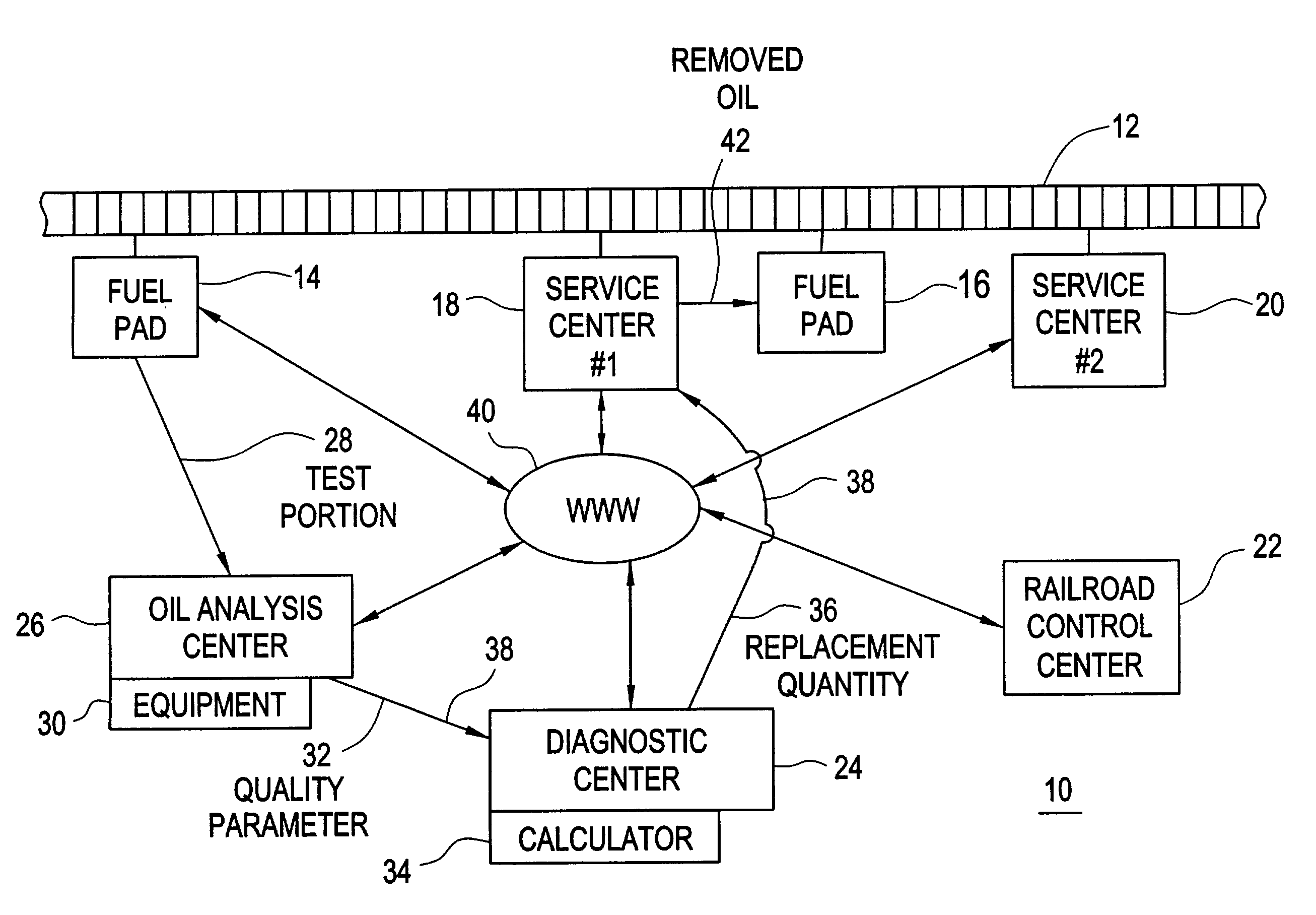
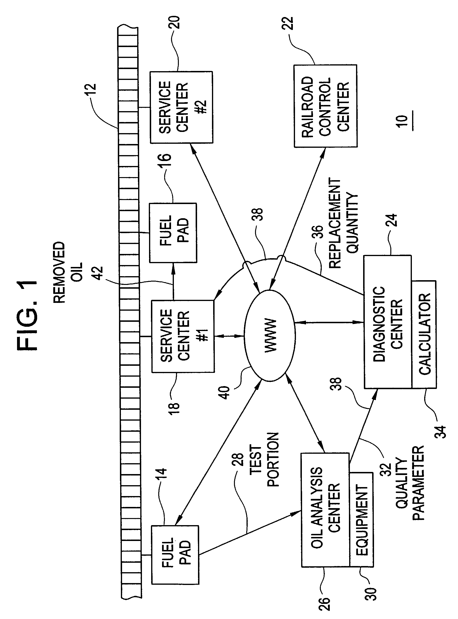
[0012]FIG. 1 illustrates one embodiment of a system 10 for maintaining the quality of lubricant in an engine of a vehicle during a period of operation between successive service outages. The engine may be a diesel internal combustion engine of a locomotive (not shown) operating on a rail system 12. The rail system 12 includes a plurality of fueling locations, such as fuel pads 14, 16 and a number of service locations, such as service centers 18, 20. A fuel pad 16 may be co-located and associated with a service center 18. The operation of locomotives and trains of rail vehicles along the rail system 12 may be controlled from a railroad control center 22. A diagnostic center 24 may be associated with the rail system 12 and the railroad control center 22 for performing a variety of technical and economic diagnostic functions designed to improve the operating efficiency of the rail system 12. One such diagnostic center 24 operated by the assignee of the present invention is located in E...


PUM


Abstract

A system (10) for ensuring the quality of lubricating oil in an engine of a locomotive without the need for specialized diagnostic and fluid handling systems on the locomotive. A test portion (28) of lubricating oil is removed from the engine and is analyzed at an oil analysis center (26) to determine an oil quality parameter (32). The oil quality parameter is used as an input to a calculator (34) to determine a quantity of oil (36) that must be replaced by fresh oil during a current maintenance outage in order to ensure that the engine oil quality will remain acceptable throughout a forthcoming operating period. In this manner, a complete change-out of the lubricating oil may be delayed or avoided. The oil replacement decision and quantity is communicated to a service center (18) via a communications link such as the Internet (40) prior to the arrival of the locomotive at the service center. The used oil may be removed from the engine using a portable transfer device and mixed with fuel in a fuel storage tank for subsequent refueling of other locomotives.

Description

CROSS-REFERENCE TO RELATED APPLICATION[0001]This application claims benefit of the Feb. 5, 2002, filing date of U.S. provisional application No. 60 / 354,658.FIELD OF THE INVENTION[0002]This invention relates to the field of lubricating oil management systems for the internal combustion engine of a vehicle.BACKGROUND OF THE INVENTION[0003]An internal combustion engine relies upon a lubricating fluid, typically natural or synthetic oil, to reduce friction between moving parts and to remove heat from critical components of the engine. It is well known that the desirable properties of such fluids will degrade with continued operation of the engine, due to chemical changes in the fluid itself as well as the accumulation of contaminants that cannot be successfully filtered out of the fluid.[0004]Many schemes are used to maintain the quality of lubrication in the internal combustion engine of a vehicle. Lubricating oil may be removed and replaced after a predetermined time period, after a p...

Claims


Application Information

Patent Timeline
IPC IPC(8): G06Q10/00G06Q30/00F01M1/18
CPCF01M1/18F01M2011/14F01M11/0458
Inventor DAYAL, BHUPINDER SINGHKRALIK, JOHN PAULCONDRAN, KEITH A.CRYER, ROBERT DOUGLASSONNEY, THOMAS CHARLES
Owner GE GLOBAL SOURCING LLC
Why Eureka
Try Eureka