Light emitting device with ceramic conversion material

a technology of light-emitting devices and conversion materials, which is applied in the direction of printers, instruments, therapy, etc., can solve the problems of inability to maintain the light flux, the color temperature of the light cannot be changed without deterioration, and the light cannot shift to the red. achieve the effect of maintaining or maintaining

Active Publication Date: 2014-04-01
KONINKLIJKE PHILIPS ELECTRONICS NV
View PDF36 Cites 15 Cited by
  • Summary
  • Abstract
  • Description
  • Claims
  • Application Information

AI Technical Summary

Benefits of technology

[0006]It is therefore an object of the present invention to provide a light delivery device, especially a light delivery device for medical purposes, which allows a change in color temperature while essentially maintaining or even improving the light flux and / or light density.

Problems solved by technology

However, in prior art applications there is no possibility to change the color temperature of the light without deterioration of the light flux and / or light density.
For example in halogen lamps it is possible to decrease the color temperature (increase the red emission relative to green and blue) by simply diminishing the light flux, but a shift towards the red while maintaining the light flux is impossible.

Method used


Image

  • Light emitting device with ceramic conversion material
  • Light emitting device with ceramic conversion material
  • Light emitting device with ceramic conversion material

Examples


example i

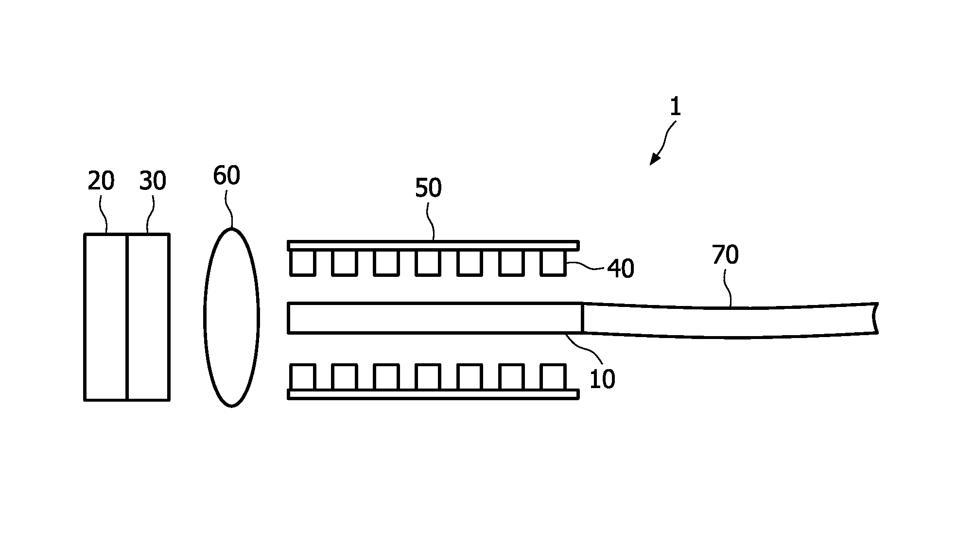
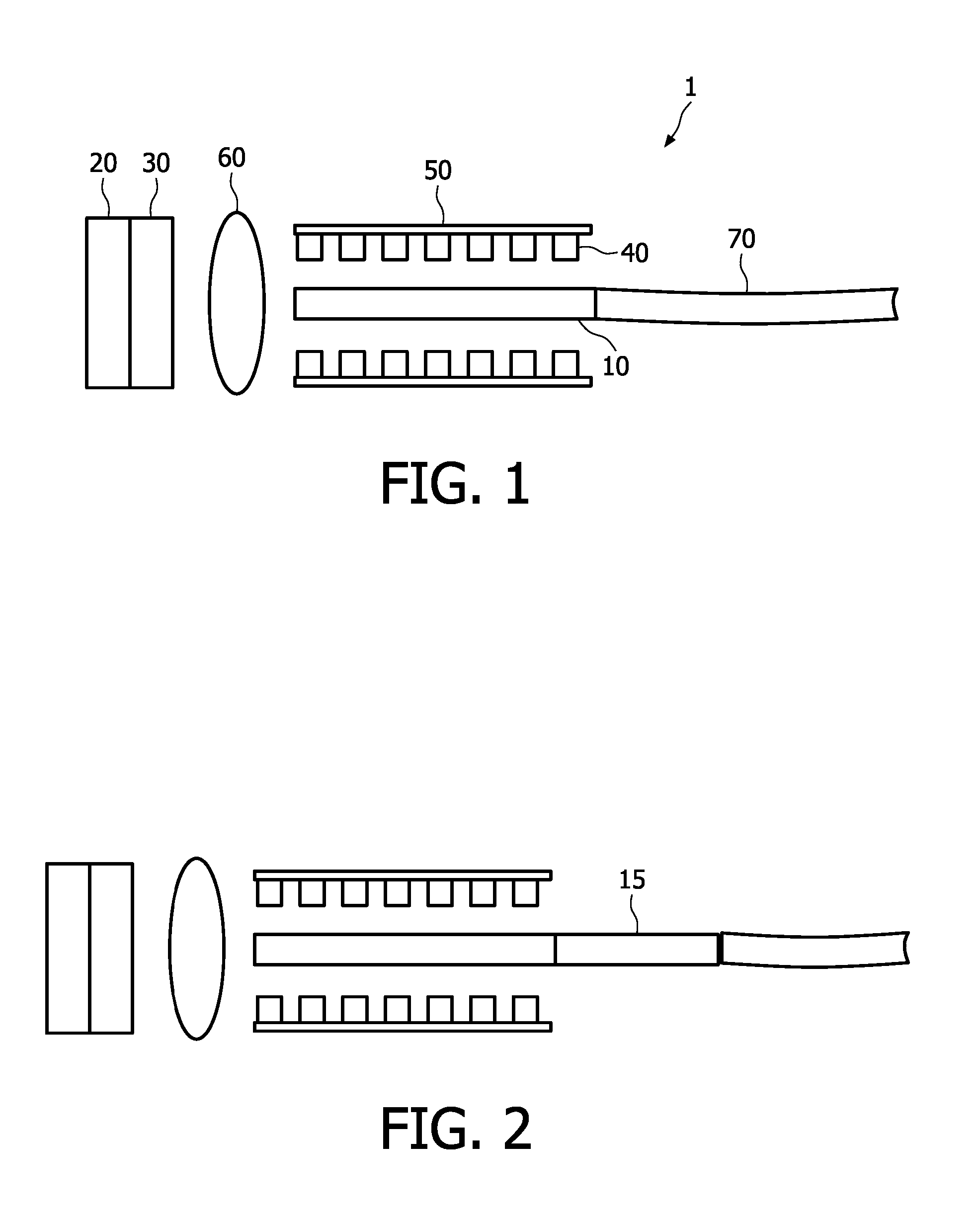
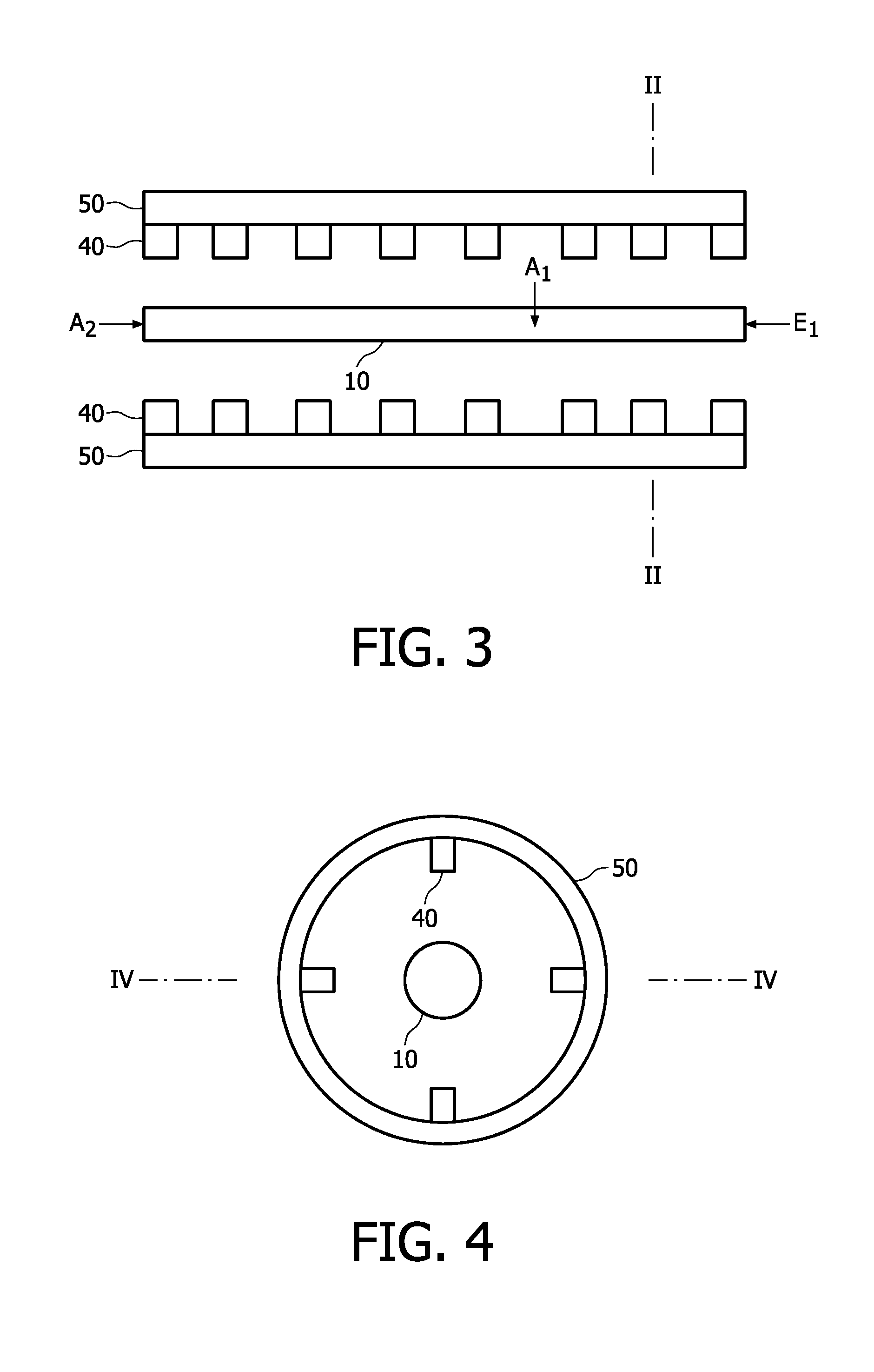
[0083]In Example I, a light delivery device with the setting of FIG. 1 was used. The first LED (reference no. 20 in FIG. 1) was a InGaN LED with a peak emission at 462 nm, the first converter substance (reference no. 30 in FIG. 1) was a YAG:Ce ceramic material with the composition Y(3-x-y)GdxAl5O12:Cey with x=0.3 and y=0.06.

[0084]The conversion element (reference no. 10 in FIG. 1) was Y2O3:Eu with a 7% Europium doping and a density of 5.029 g / cm3.

[0085]The light delivery device furthermore comprises two sets of auxiliary LEDs (reference no. 40 in FIG. 1), which are also InGaN LEDs. Each set of LEDs has a power of 100% of the first LED and a peak emission at 465 nm.

[0086]FIGS. 5 and 6 show the spectra of the light delivery device with the first LED only (“LED”), with one set of auxiliary LEDs switched on (“Aux1”) and with both sets of auxiliary LEDs switched on (“Aux2”).

[0087]The data of FIGS. 5 and 6 are listed in Table I

[0088]

TABLE ILEDAux1Aux23800.001880.002380.002883820.0017390.0...

example ii

[0093]In Example II, a light delivery device with the setting of FIG. 1 was used. The first LED (reference no. 20 in FIG. 1) was an InGaN LED with a peak emission at 462 nm, the first converter substance (reference no. 30 in FIG. 1) was a YAG:Ce ceramic material with the composition Y(3-x-y)GdxAl5O12:Cey with x=0.3 and y=0.06.

[0094]The conversion element on Example II is CaS:Eu with 0.1% Europium.

[0095]The light delivery device furthermore comprises two sets of auxiliary LEDs (reference no. 40 in FIG. 1), which are also InGaN LEDs emitting at 450 nm. Each set of LEDs has a “strength” of 50% of the first LED.

[0096]FIG. 7 shows the spectra of the light delivery device with the first LED only (“LED”), with one set of auxiliary LEDs switched on (“Aux1”) and with both sets of auxiliary LEDs switched on (“Aux2”).

[0097]The data of FIG. 7 are listed in Table III:

[0098]

TABLE IIILEDAux 1Aux 23800.0027310.0028110.0028913820.002460.002540.002623840.0022950.0023750.0024553860.0021830.0022630.002...


PUM

PropertyMeasurementUnit
wavelength rangeaaaaaaaaaa
angleaaaaaaaaaa

Abstract

A lighting device including at least one conversion element and a least one LED, which emits light into the conversion element. The light is then converted and emitted with a high radiant flux. The at least one LED emits light in the wavelength range of ≧220 nm to ≦800 nm and the at least one conversion element converts at least part of the light from the at least one LED to light in the wavelength range of >300 nm to <1000 nm. In some embodiments, the at least one conversion element includes a ceramic conversion material.

Description

FIELD OF THE INVENTION[0001]This invention relates to the field of light delivery devices, especially light delivery devices which are used for medical purposes, such as endoscopy.BACKGROUND OF THE INVENTION[0002]In endoscopy devices, light is delivered to a body lumen or body cavity, e.g. for diagnostic purposes as well as photodynamic therapy of atherosclerosis, malignant or benign tumor tissue, cancerous cells and other medical treatments. Devices of the prior art are disclosed in e.g. the US 2005 / 0165462, which is incorporated herein by reference.[0003]Especially in endoscopy devices, which are used for diagnosis, a light source with a high flux density is used, such as Xenon lamps and halogen lamps. However, in prior art applications there is no possibility to change the color temperature of the light without deterioration of the light flux and / or light density. The term ‘color temperature’ is used in lieu of the definition of the correlated color temperature of a light source....

Claims


Application Information

Patent Timeline
Patent Type & Authority Patents(United States)
IPC IPC(8): F21V9/10H05B44/00F21V9/40
CPCA61B1/00117A61B1/0653A61B1/0669A61N5/0601A61N5/0603A61N5/062A61N2005/0652A61N2005/0662G02B6/0003G02B6/0006A61B1/0684H05B45/20
Inventor HOFMANN, BERNDBECHTEL, HANS-HELMUT
Owner KONINKLIJKE PHILIPS ELECTRONICS NV
Why Eureka
Try Eureka