Crankcase structure for an internal combustion engine

a crankcase and internal combustion engine technology, applied in the direction of machines/engines, cycles, transportation and packaging, etc., can solve the problems of difficult to maintain the strength of the left wall of the crankcase in the periphery of the rear wheel, subject to a large load, etc., and achieve the effect of increasing the weigh

Inactive Publication Date: 2010-07-20
HONDA MOTOR CO LTD
View PDF3 Cites 11 Cited by
  • Summary
  • Abstract
  • Description
  • Claims
  • Application Information

AI Technical Summary

Benefits of technology

[0010]In view of the above problems, it is an object of the present invention to provide a crankcase structure of an internal combustion engine in which the strength of a side wall of a crankcase is maintained at a high level without increasing the weight and the size of the internal combustion engine to desirably support shafts, even when the internal combustion engine is provided with an output shaft that projects from the crankcase.
[0016]According to the first aspect of the present invention, the crankshaft and the counter shaft are rotatably supported on the partitioning plane of the crankcase including the upper and lower halves oriented in the fore-and-aft direction. The main shaft oriented in the fore-and-aft direction is rotatably supported on the opposed front and rear walls of either one of the upper and lower crankcases. Therefore, the lateral width of the internal combustion engine may be reduced by arranging the crankshaft, the main shaft and the counter shaft at the respective apexes of a triangle. The output shaft penetrates through the front and rear walls of one of the upper and lower crankcases by which the main shaft is not rotatably supported, and projects to the front and rear. Therefore, the shaft support of the crank case may be dispersed. Hence, shaft support may be achieved desirably without upsizing the internal combustion engine.
[0017]According to the second aspect of the present invention, the bearing opening for rotatably supporting the other end of the main shaft via the second bearing is formed on the other side wall so as to have an inner diameter larger than the transmission gear at the outermost end of the other end on the main shaft. The bearing opening of the other side wall of the crankcase is used as an opening for assembling the main shaft. Therefore, the main shaft having the transmission gear group assembled thereto may be inserted into the bearing opening to achieve assembly of the main shaft and the assembleability of the main shaft may desirably be secured.
[0018]Therefore, it is not necessary to use the bearing recess for rotatably supporting the one end of the main shaft via the first bearing at one end as the opening for assembling the main shaft and hence the inner diameter may be reduced. Therefore, even when the bearing opening for rotatably supporting the counter shaft formed adjacent thereto is formed to have a large diameter for fitting the large bearing for resisting a load applied to the output members, the strength of the side wall of the crankcase in the periphery of the output members may be maintained at a high level.
[0019]According to the third aspect of the present invention, the one end of the main shaft of the inner cylinder having a small diameter is rotatably supported by the bearing recess of the one side wall via the first bearing. Therefore, the inner diameter of the bearing recess may be reduced. Hence, the strength of the side wall of the crankcase in the periphery of the output members provided on the counter shaft may be maintained at a higher level.
[0021]According to the fifth aspect of the present invention, the pair of transmission clutches for controlling transmission of power to the outer cylinder and the inner cylinder respectively are assembled respectively to the outside portion of the outer cylinder that projects outward from the bearing opening of the other side wall and the outside portion of the inner cylinder that projects further outward from the outer cylinder. Therefore, the pair of transmission clutches may be assembled to the outer portion of the outer cylinder and the outer portion of the inner cylinder projecting outward from the crankcase. Hence, assembly of the transmission clutches may be achieved easily.

Problems solved by technology

The left bearing opening for supporting the counter shaft is located near the rear wheel drive sprocket and hence is subject to a large load.
Therefore, it is difficult to maintain the strength of the left wall of the crankcase in the periphery of the rear wheel drive sprocket, which is to be fitted to the counter shaft.

Method used


Image

  • Crankcase structure for an internal combustion engine
  • Crankcase structure for an internal combustion engine
  • Crankcase structure for an internal combustion engine

Examples


Embodiment Construction

[0030]The present invention will now be described in detail with reference to the accompanying drawings, wherein the same reference numerals will be used to identify the same or similar elements throughout the several views. It should be noted that the drawings should be viewed in the direction of orientation of the reference numerals.

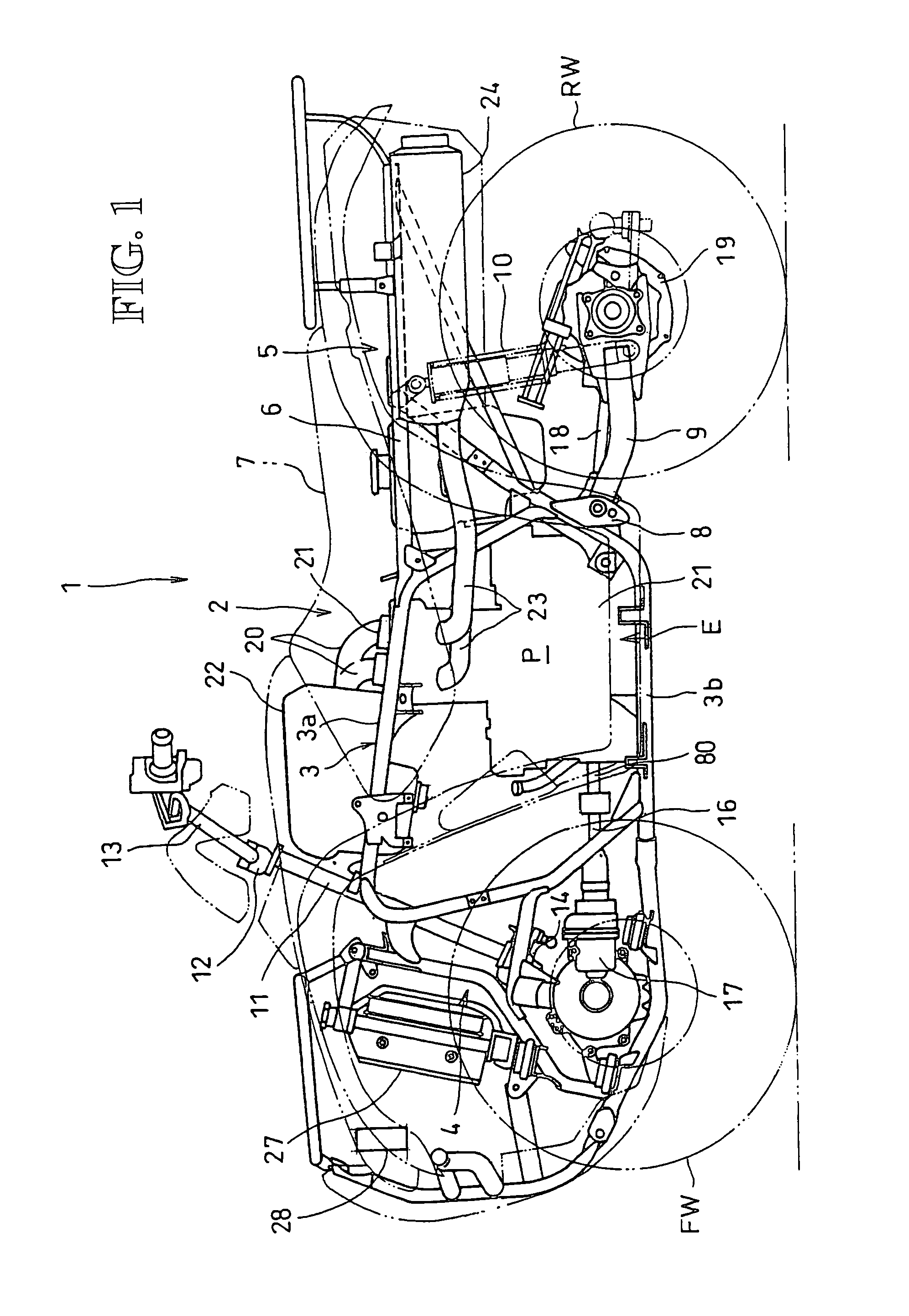
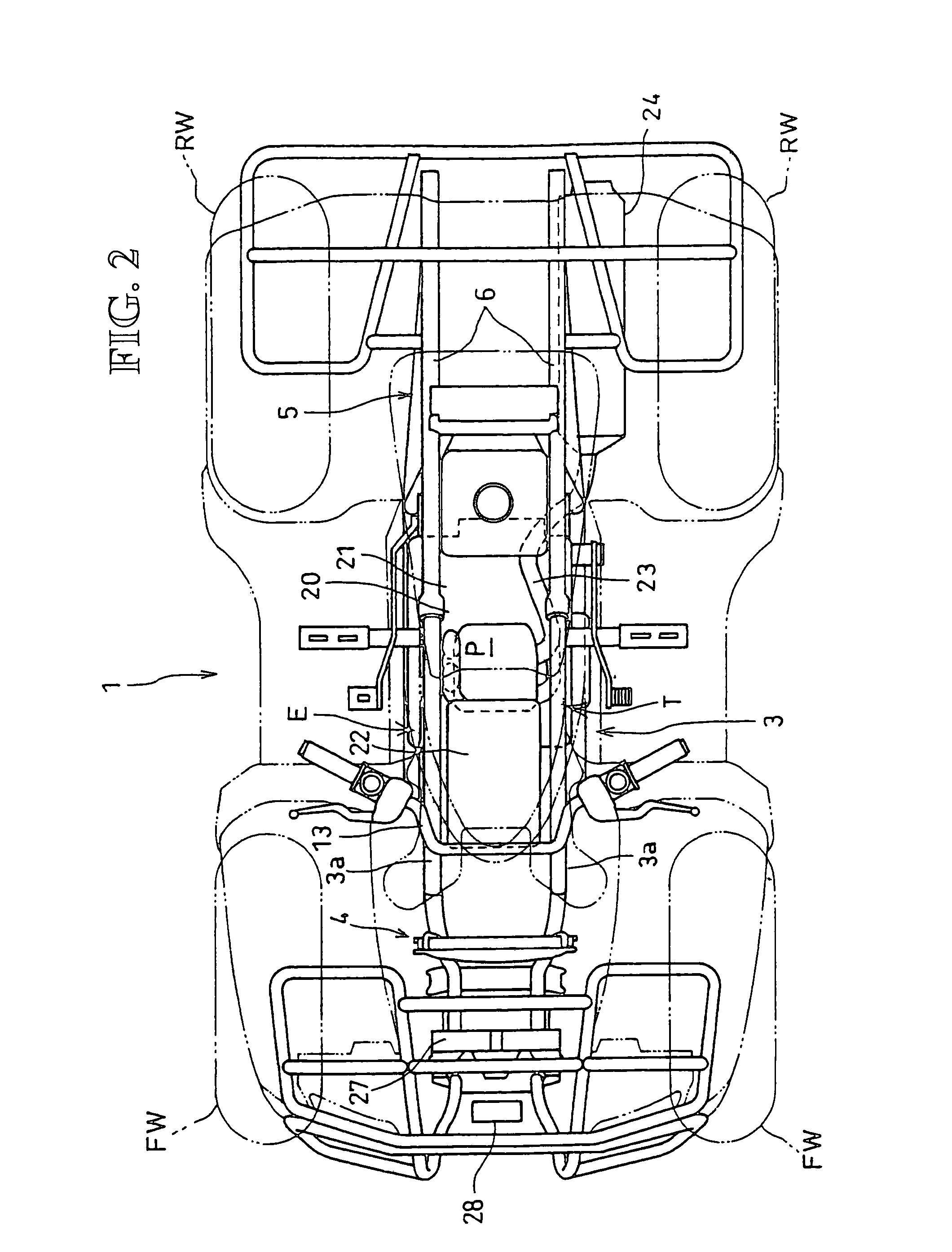
[0031]Referring now to FIG. 1 to FIG. 6, an embodiment of the present invention will be described. A side view of a rough-terrain traveling vehicle 1 in which a water-cooled internal combustion engine E according to this embodiment is mounted with a vehicle body cover or the like removed is shown in FIG. 1. A plan view of the same is shown in FIG. 2. In this embodiment, the front, rear, left and right are defined on the basis of the direction of travel of the vehicle.

[0032]The rough-terrain traveling vehicle 1 is a saddle type four-wheel vehicle, and a pair of left and right front wheels FW on which low-pressure balloon tires for rough-terrain are moun...


PUM


Abstract

A crankcase structure of an internal combustion engine has a desirable shaft support achieved by maintaining the strength of a side wall of a crankcase at a high level without increasing the weight and the size of the internal combustion engine even when the internal combustion engine has an output shaft projecting from the crankcase. A crankcase structure has a crankshaft and a counter shaft that are rotatably supported on a partitioning plane of a crankcase. A main shaft is oriented in the fore-and-aft direction and is rotatably supported on opposed front and rear walls of either one of the upper and lower crankcases. An output shaft to be driven by a power of the counter shaft penetrates through the front and rear walls of one of the upper and lower crankcases by which the main shaft is not rotatably supported, and projects to the front and rear.

Description

CROSS-REFERENCE TO RELATED APPLICATIONS[0001]This nonprovisional application claims priority under 35 U.S.C. §119(a) on Patent Application No. 2006-261277, filed in Japan on Sep. 26, 2006, the entirety of which is incorporated herein by reference.BACKGROUND OF THE INVENTION[0002]1. Field of the Invention[0003]The present invention relates to a crankcase structure of an internal combustion engine.[0004]2. Background of the Invention[0005]In an internal combustion engine, a crank shaft and a counter shaft are rotatably supported on a partitioning plane by being sandwiched between an upper crankcase and a lower crankcase of a crankcase configured to have upper and lower halves. A main shaft is rotatably supported by the upper crankcase. Output members such as an output sprocket or an output gear are fitted to an end portion of the counter shaft projecting outward from the crankcase, to drive a rear wheel via a chain, or to drive an output shaft through meshing of gears.[0006]An example...

Claims


Application Information

Patent Timeline
Patent Type & Authority Patents(United States)
IPC IPC(8): F02B75/22F02B75/00B60K17/06B62K5/00B62K5/01F02B61/02F02B61/06
CPCF02B61/02F02B67/04F02B75/06
Inventor INUI, HIROATSUSUMI, HIROMIKITTAKA, EIJI
Owner HONDA MOTOR CO LTD
Why Eureka
Try Eureka