
Power connections and interface for compact illuminator assembly

a compact, illuminator technology, applied in the direction of instruments, lighting and heating equipment, optical elements, etc., can solve the problems of inconvenient use of tethered illumination assemblies that require an ac or similar power source, inconvenient use of tethered illumination assemblies, access to tethered illumination assemblies, etc., to achieve less heat dissipation, less shock, and longer service life

Inactive Publication Date: 2010-07-20
WELCH ALLYN INC
View PDF182 Cites 49 Cited by
  • Summary
  • Abstract
  • Description
  • Claims
  • Application Information

AI Technical Summary

Benefits of technology

The patent describes an illuminator assembly that includes a portable illuminator, a primary power source, and a charging station. The portable illuminator has an interface that can connect to the charging station, allowing for easy swapping of the primary power source. The charging station has an engagement member that securely holds the illuminator in place during charging. The illuminator can also have a rechargeable battery that can be recharged using the charging station. The charging station can be a separate device or a part of the illuminator itself. The illuminator can also have a base that includes a light source and a charging port for the primary power source. The engagement members of the illuminator and the charging station can be different interfaces that are commonly connectable. The portable illuminator is reusable and the speculum (a disposable part of the assembly) is disposable. The charging station includes an engagement member that securely holds the illuminator in place during charging. The charging station can also have a spring-biased engagement member that can be moved to retain the illuminator in an upright and electrically engaged state. The auxiliary power module can be a separate device or a part of the illuminator itself.

Problems solved by technology

A number of problems have been discovered in the use and maintenance of such apparatus.
For example, the use of a tethered illumination assembly that requires an AC or similar power source is often inconvenient in the field, particularly remote areas in which access to such a power supply is uncertain.
In addition, the use of a tethered illumination assembly presents access and other issues, for example, with bed-ridden patients.
There are similar concerns relating to the use of incandescent lamps as a light source in that such sources are typically sealed within the housing of the illumination assembly and are subject to breakage, for example, if the illumination assembly is dropped.
Incandescent lamps produce significant heat, which is a concern to both the caregiver and the patient, and have a finite service life, requiring periodic teardown or replacement of the entire illumination assembly.
In addition, incandescent lamps are relatively expensive, as compared, for example, with other types of commercially available light sources, thereby impacting the cost of such apparatus.
Though there is a desired need to be able to provide a portable power source to permit versatility in patient examinations, this need has been further frustrated with a competing need to enable the portable power source to conveniently be recharged or otherwise supplemented and / or bypassed or replaced, if needed.

Method used


Image

  • Power connections and interface for compact illuminator assembly
  • Power connections and interface for compact illuminator assembly
  • Power connections and interface for compact illuminator assembly

Examples


Embodiment Construction

[0055]The following embodiment details the use of a portable illuminator as used with a vaginal speculum assembly wherein the illuminator can also be independently used as an examination light. Various terms are used throughout to provide a suitable frame of reference with regard to the accompanying drawings such as “lower”, “upper”, “top”, “bottom”, “within”, “lateral”, “upon”, “front”, “back”, and the like. Such terms are not intended to be overly limiting, however, except where so specifically indicated.

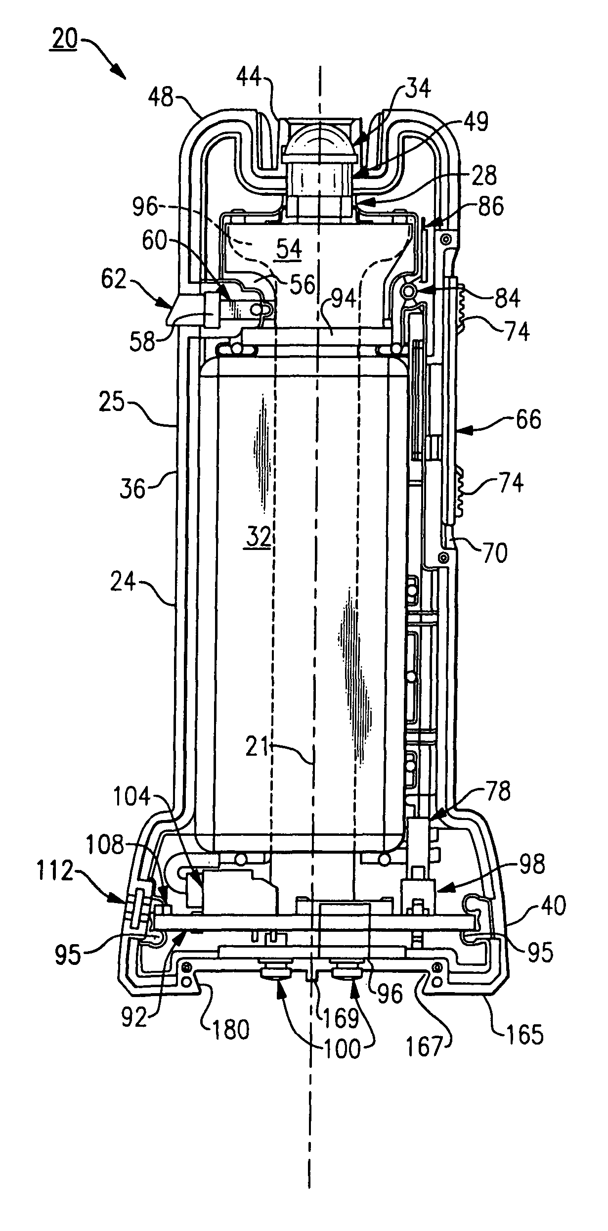
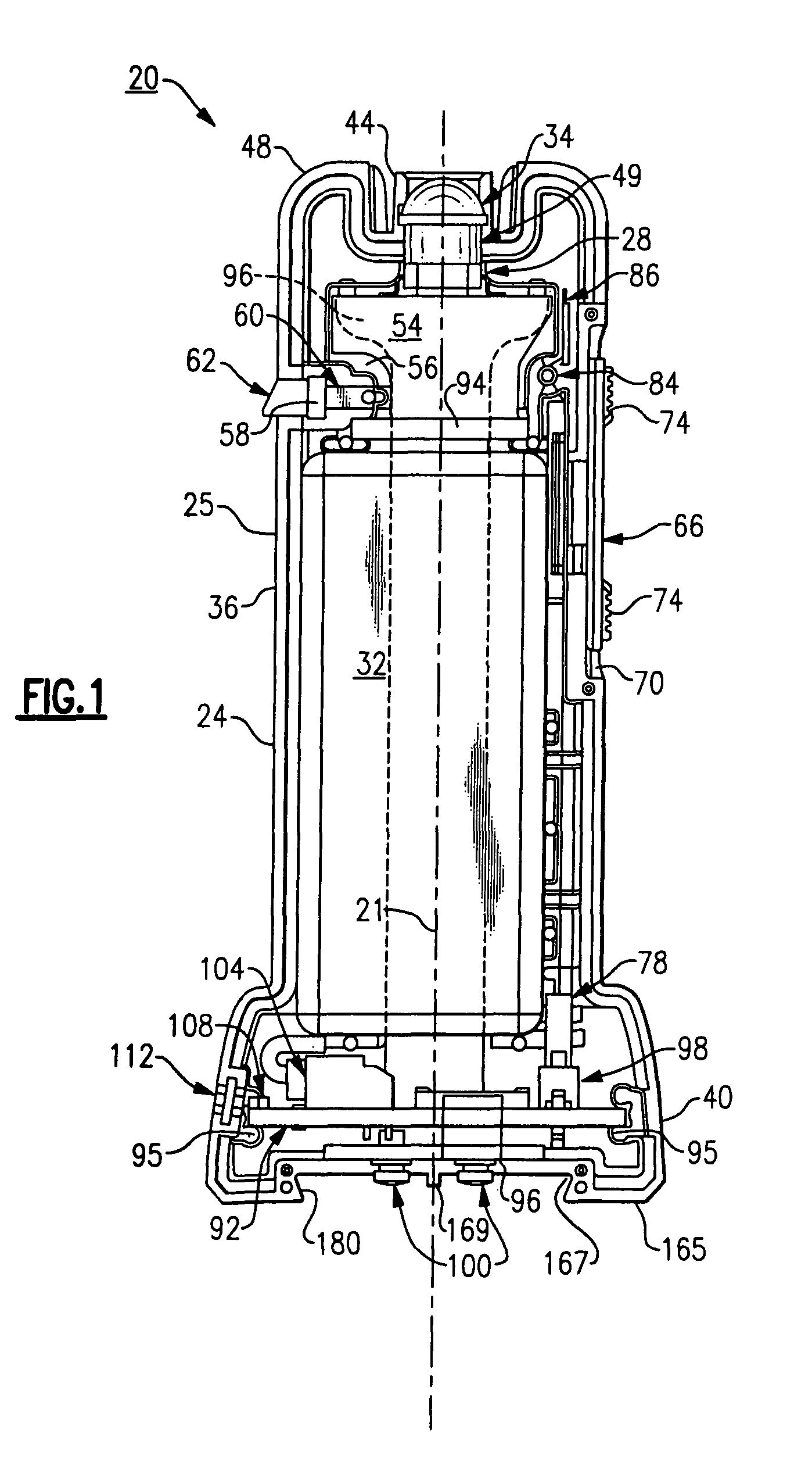
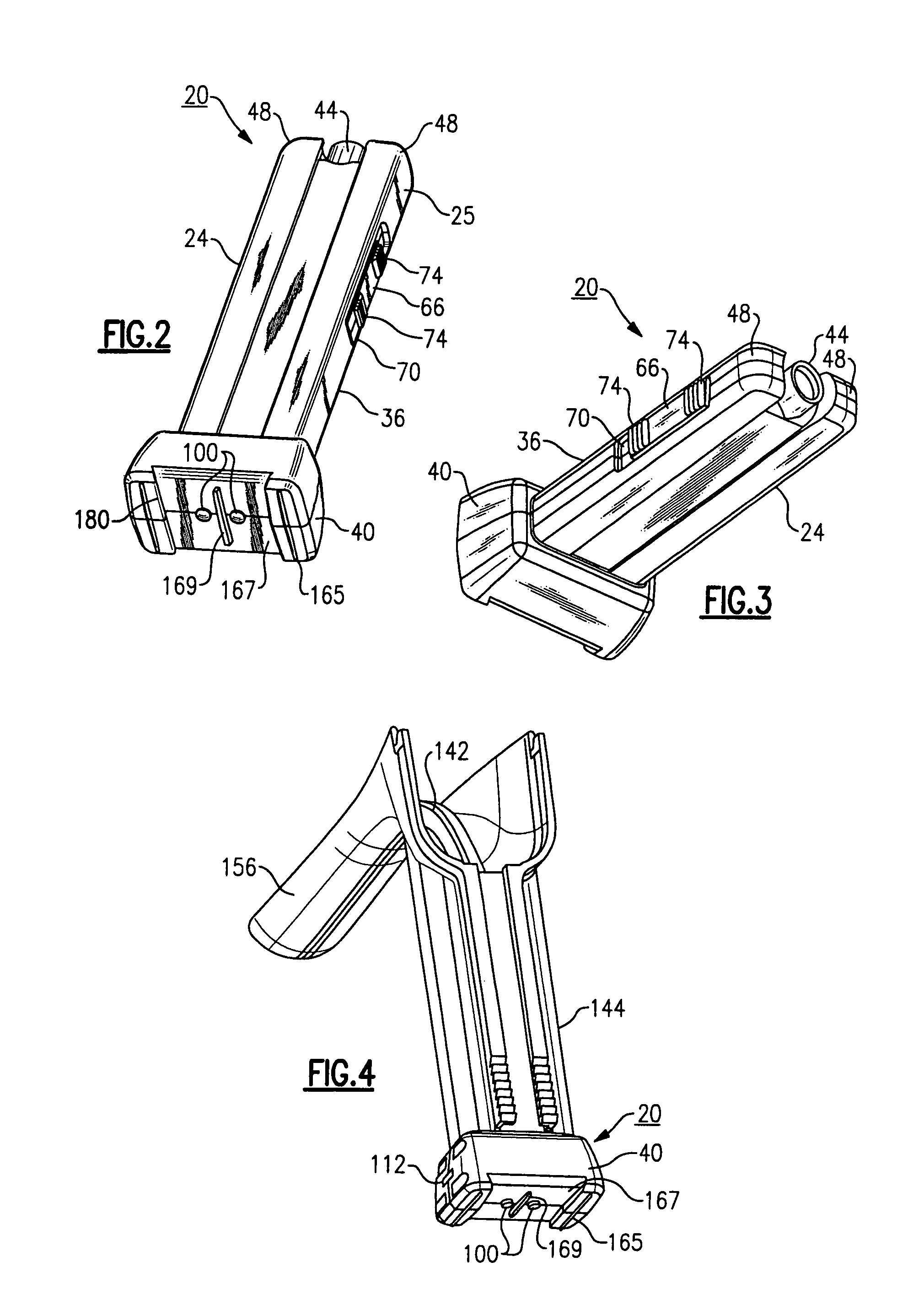
[0056]Referring to FIG. 1, there is shown a portable illuminator 20 that is defined by a housing or body section 24 having an interior sized to retain a number of components, including, among others, at least one portable light source and at least one portable power supply. According to the specific embodiment described herein, the portable light source is a white LED 28, such as, for example, those manufactured and sold by Nichia America, Inc. and Lumileds, Inc., while the portab...


PUM


Abstract

A portable illuminator includes a contained power source and an integrally contained light source that is selectively inserted into the handle portion of a vaginal speculum. The portable illuminator includes an electrical interface that permits selective connection to at least two electrical devices for purposes of at least one of supplementing, replacing and recharging the contained power source.

Description

CROSS REFERENCE TO RELATED APPLICATIONS[0001]This application is a nonprovisional application filed under 35 U.S.C. §119 and based upon U.S. Ser. No. 60 / 876,346, filed Dec. 21, 2006. This application is also a continuation in part (CIP) application filed under 35 U.S.C. §120 of PCT PCT / US2006 / 12116, filed Apr. 3, 2006, PCT / US 2006 / 12320, filed Apr. 3, 2006, and PCT / US2006 / 012322, filed Apr. 3, 2006. This application also further relates to commonly assigned and concurrently filed U.S. Ser. No. 11 / 731,631, the entire contents of each of the preceding documents being incorporated by reference herein.FIELD OF THE INVENTION[0002]The invention relates to the field of diagnostic medical devices and in particular to a portable illuminator containing a primary power source. The portable illuminator has an interface that enables use with at least two different electrical devices in order to recharge, supplement and / or replace the contained primary power source.BACKGROUND OF THE INVENTION[000...

Claims


Application Information

Patent Timeline
Patent Type & Authority Patents(United States)
IPC IPC(8): F21L4/00A61B1/00F21S4/00
CPCA61B1/303A61B1/32A61B1/00032A61B1/00105A61B1/0669A61B1/0684
Inventor MCMAHON, MICHAEL T.SLAWSON, STEVEN R.SADDLEMIRE, DALE C.
Owner WELCH ALLYN INC
Learn More