Numerical controller and synchronous control method using numerical controller

a numerical controller and synchronous control technology, applied in the field of numerical controllers, can solve the problems of affecting the decrease of the cycle time and the kind of loss time, and achieve the effect of reducing the cycle time and losing tim

Inactive Publication Date: 2010-07-20
FANUC LTD
View PDF11 Cites 1 Cited by
  • Summary
  • Abstract
  • Description
  • Claims
  • Application Information

AI Technical Summary

Benefits of technology

[0009]It is an object of the present invention to provide: a numerical controller which solves the above mentioned problem in a synchronous control for making a follow-up axis catch up with a follow-up target axis for synchronization, that is, a problem of loss time which is generated because the advanced operation not related to the synchronization and the processing for this operation are executed after completion of synchronization, and can decrease the cycle time in a application which performs synchronous control; and a control method using this device.
[0015]Hence the processing of an operation which is executed in synchronized status and an operation based on this processing can be started immediately after the advanced operation. In other words, loss time, which is generated because the advanced operation not related to synchronization and processing for this operation are executed after synchronization completion, can be decreased, and cycle time in an application which performs synchronous control can be easily decreased.

Problems solved by technology

This means that time required for processing for the advanced operation, which is not related to synchronization, and the execution of an operation based on this processing elapses after completion of synchronization and processing for operation, which is related to synchronization and execution of an operation based on this processing delays accordingly.
This generates a kind of loss time, and interferes with a decrease in the cycle time in an application which performs synchronous control.

Method used


Image

  • Numerical controller and synchronous control method using numerical controller
  • Numerical controller and synchronous control method using numerical controller
  • Numerical controller and synchronous control method using numerical controller

Examples


Embodiment Construction

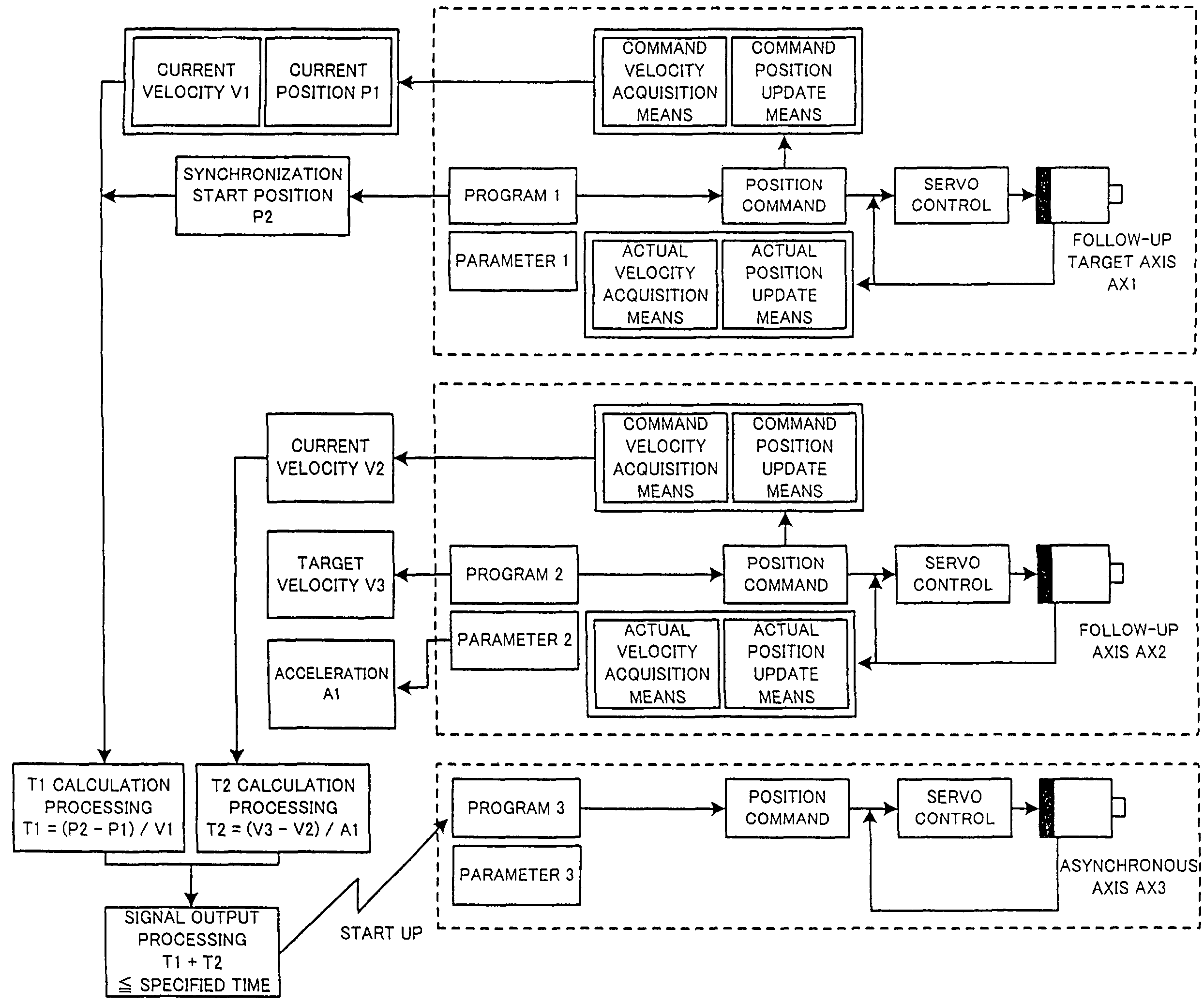
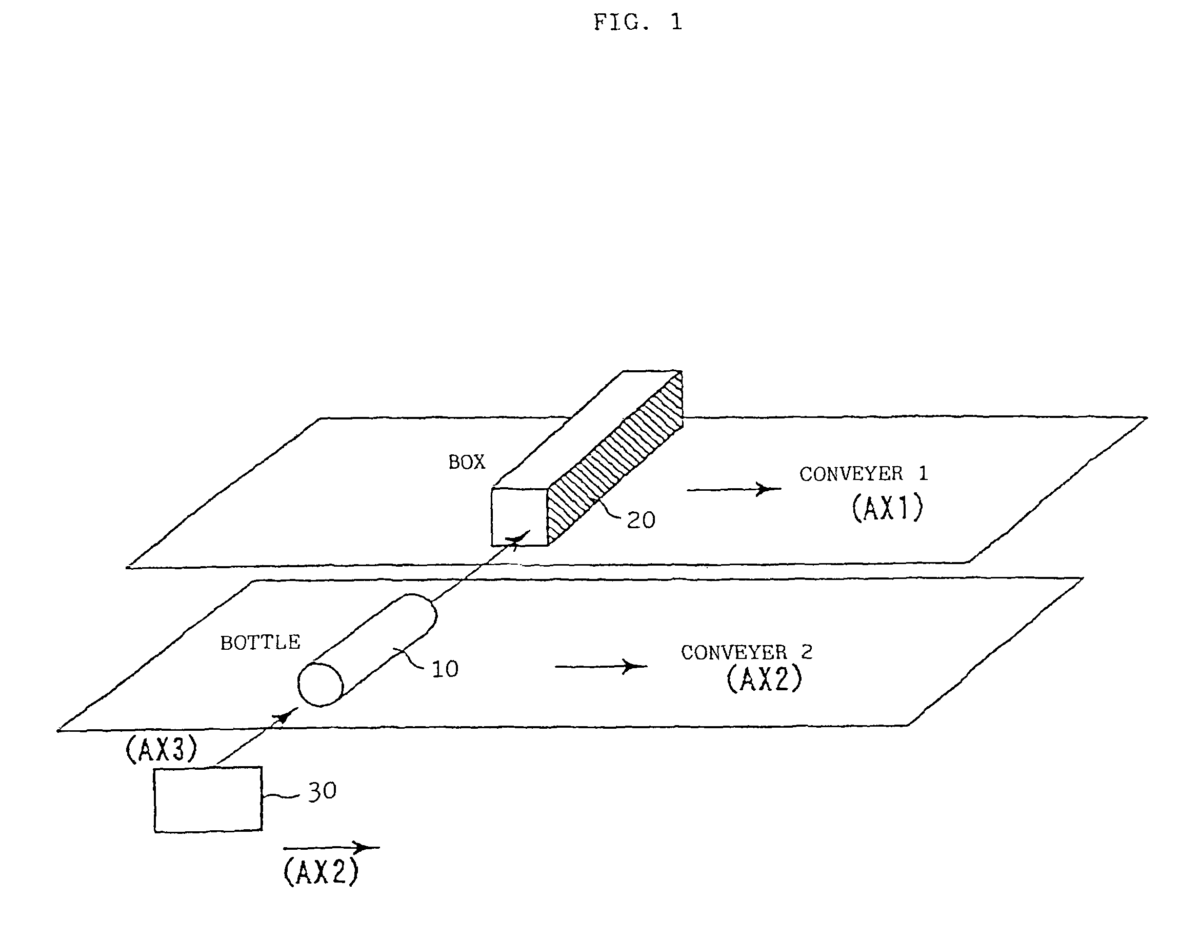
[0022]FIG. 1 shows an example of an application where the present invention is applied to synchronous control for a follow-up axis to catch up with and synchronize with a follow-up target axis. As FIG. 1 shows, this application is for performing an operation of inserting a bottle 10 (an example of an object to be moved with a moving object at the same velocity) into a box (an example of the moving object) 2 which is moving by a conveyer 1, using the operation of two synchronizing axes AX1 and AX2, and an asynchronous axis AX3.

[0023]A first axis AX1 is an axis for moving the conveyer 1 from the left to the right direction in FIG. 1, and becomes a “follow-up target axis” from the synchronization start point to the clearing of the synchronization status (hereinafter referred to as “during synchronization”). A second axis AX2, on the other hand, is an axis for moving a conveyer 2 in a same direction as the conveyer 1, and becomes “follow-up axis” during synchronization. The box 20 has a...


PUM


Abstract

A conveyer for transporting a box and a conveyer for transporting a bottle are driven along a follow-up target axis and a follow-up axis, respectively. The follow-up axis is accelerated from a synchronization start position, and, when the follow-up axis velocity catches up with the conveyer, performs the constant velocity operation. An advanced operation, performed by an asynchronous axis (moving the bottle closer to the box), is started before synchronization completes, and is completed when synchronization completes, then immediately an operation by a synchronous axis (follow-up target axis or follow-up axis) is started (insertion operation). The point of time when the advanced operation is started is determined by processing of the numerical controller, as a point of time when the time required for the follow-up axis in the current status to reach the synchronization completion status becomes the same as the time required for the advanced operation (preset).

Description

BACKGROUND OF THE INVENTION[0001]1. Field of the Invention[0002]The present invention relates to a numerical controller which controls a plurality of axes, including an axis to be a follow-up target axis in synchronization and an axis to be a follow-up axis in synchronization, and a control method for performing synchronous control using the numerical controller so that the follow-up axis follows up the follow-up target axis.[0003]2. Description of the Related Art[0004]In an application for moving a tool in stopping status and processing a work which is moving by a conveyer driven by an axis, for example, synchronous control is performed by synchronizing a drive axis (follow-up axis) of moving means (e.g. slider) of a tool with an axis (follow-up target axis) for driving the conveyer.[0005]In this case, actual processing by the tool is started after the synchronization completes (after the moving speed of the tool by the follow-up axis catches up with and matches with the moving spe...

Claims


Application Information

Patent Timeline
Patent Type & Authority Patents(United States)
IPC IPC(8): G05B19/18
CPCG05B19/195G05B19/4189G05B2219/45048G05B2219/45054G05B2219/50216Y02P90/02
Inventor HISHIKAWA, TETSUOHIROSE, NOBORU
Owner FANUC LTD
Why Eureka
Try Eureka