Vision system with deterministic low-latency communication

a vision system and low-latency communication technology, applied in the field of machine vision, can solve problems such as insufficient prior art transmission media and protocols for vision system operation, and achieve the effect of low latency

Active Publication Date: 2010-07-20
NATIONAL INSTRUMENTS
View PDF13 Cites 15 Cited by
  • Summary
  • Abstract
  • Description
  • Claims
  • Application Information

AI Technical Summary

Problems solved by technology

However, as the characteristic frequencies of machine vision systems increase, e.g., due to faster processors, prior art transmission media and protocols may be inadequate for operation of vision systems, particularly in applications where cooperative operation between multiple devices is required.

Method used


Image

  • Vision system with deterministic low-latency communication
  • Vision system with deterministic low-latency communication
  • Vision system with deterministic low-latency communication

Examples


Embodiment Construction

Incorporation by Reference

[0029]The following references are hereby incorporated by reference in their entirety as though fully and completely set forth herein:

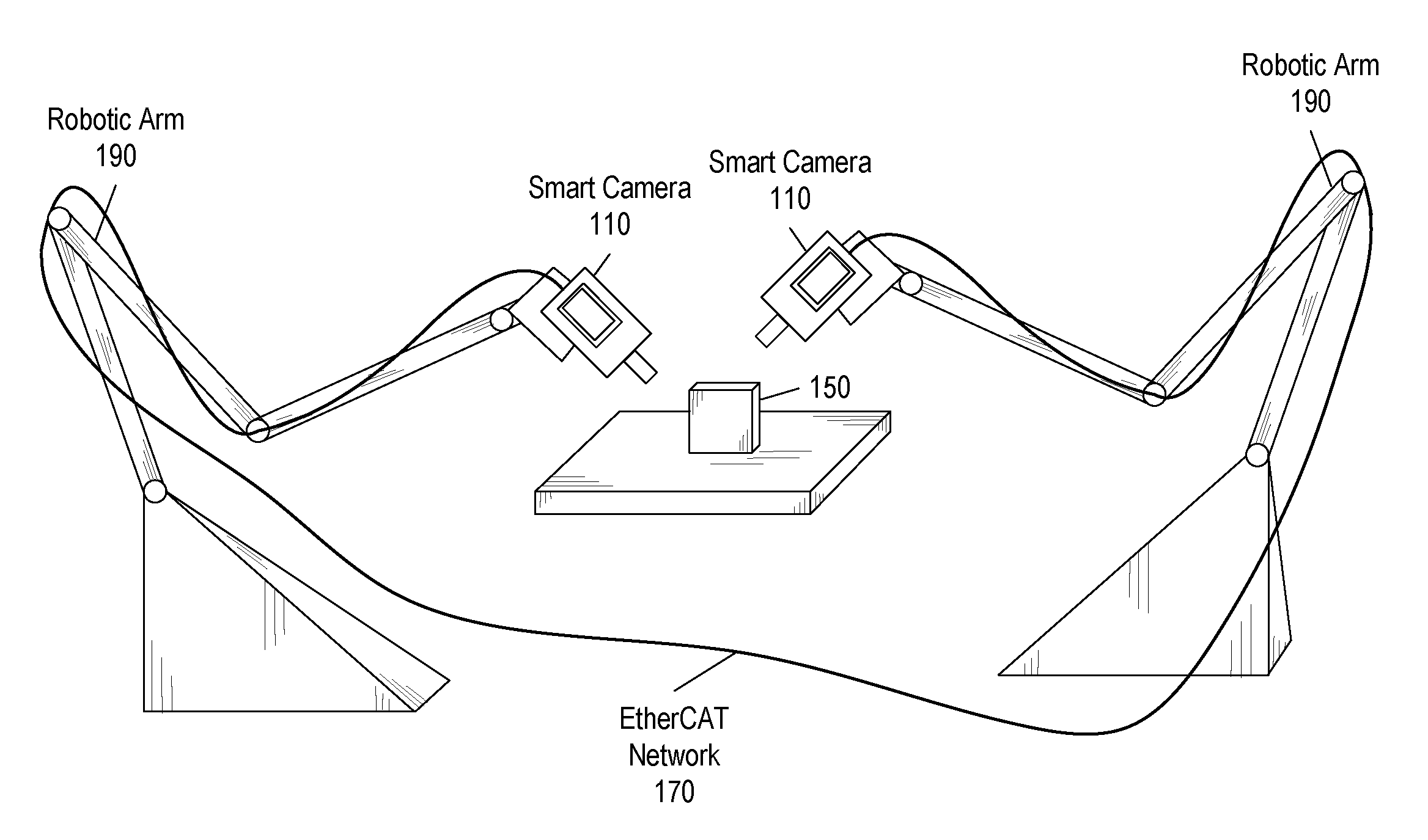
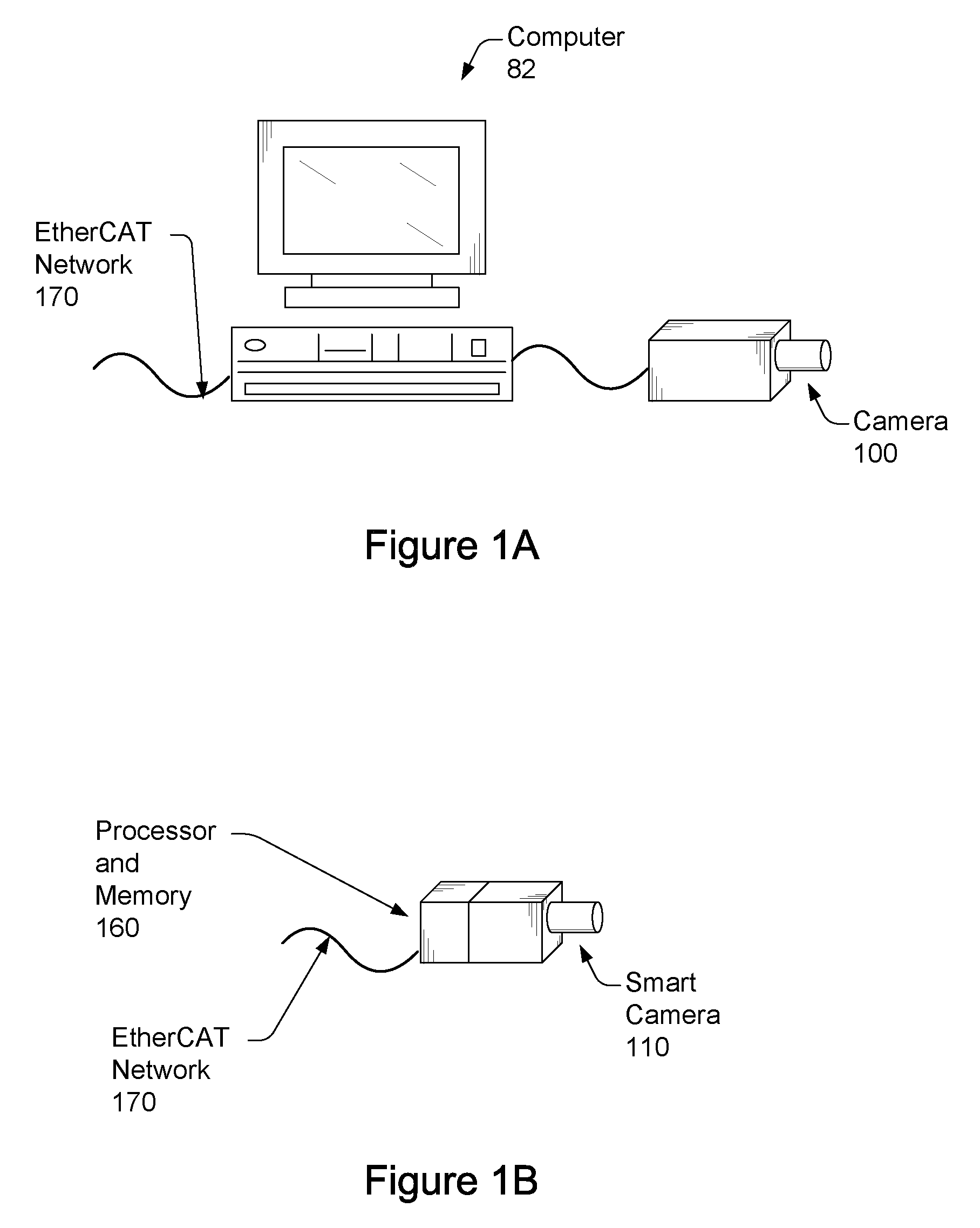
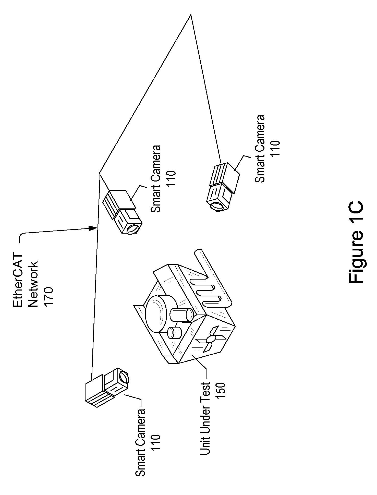
[0030]U.S. patent application Ser. No. 10 / 120,151 titled “Smart Camera With Modular Expansion Capability”, filed Apr. 10, 2002.

[0031]U.S. patent application Ser. No. 10 / 090,482 titled “Scanning System and Method which Utilizes Continuous Motion Control and Data Acquisition Triggering”, filed Mar. 1, 2002.

[0032]U.S. patent Ser. No. 10 / 809,107, titled “A Mixed Signal Analysis System and Method of Use”, filed Mar. 25, 2004.

[0033]EtherCAT Specification IEC / PAS 62407, 2005-06.

Terms

[0034]The following is a glossary of terms used in the present application:

[0035]Memory Medium—Any of various types of memory devices or storage devices. The term “memory medium” is intended to include an installation medium, e.g., a CD-ROM, floppy disks 104, or tape device; a computer system memory or random access memory such as DRAM, DDR RAM, SRAM, ED...


PUM


Abstract

Vision system and method. The system includes a vision system, including: a camera, a processor and memory, coupled to the camera, and an EtherCAT interface, coupled to the processor and memory, possibly contained in a chassis, and operable to couple to an EtherCAT network that provides for deterministic low-latency communication between the vision system and devices coupled to the EtherCAT network. The vision system may be configurable to operate as any of: an EtherCAT master device, an EtherCAT slave device, or a TCP / IP Ethernet device. One or more additional vision systems may couple to the EtherCAT network. The vision systems may be synchronized using an EtherCAT distributed clock technique, time-based triggered, and / or event triggered, via the EtherCAT network, e.g., in a multi-view vision, collaborative processing, control, I / O, or video servoing application, e.g., using an EtherCAT deterministic low latency closed loop feedback system, including processing, control, or I / O devices.

Description

FIELD OF THE INVENTION[0001]The present invention relates to the field of machine vision, and more particularly to a machine vision system with a deterministic low-latency interface.DESCRIPTION OF THE RELATED ART[0002]In many applications, machine vision systems are used to inspect or locate an object. For example, in manufacturing applications, machine vision may be used to detect defects in a manufactured object by acquiring images of the object and using various types of image processing algorithms to analyze the images. As an example, a system to manufacture electrical components such as capacitors may use machine vision to examine respective sides of the capacitors in order to detect manufacturing defects, ensure that the capacitors are labeled, marked, or color coded properly, etc.[0003]As another example, a machine vision system may be used to inform and / or control a control device, such as a motion control device. For example, following the capacitor-manufacturing example ab...

Claims


Application Information

Patent Timeline
Patent Type & Authority Patents(United States)
IPC IPC(8): H04N5/232
CPCH04N5/232H04N5/23206H04N5/247H04N23/661H04N23/90
Inventor GIESEN, ROBERT J. B.
Owner NATIONAL INSTRUMENTS
Why Eureka
Try Eureka