Apparatus and method for handling pipe

a technology of apparatus and pipe, which is applied in the direction of drilling pipes, drilling casings, borehole/well accessories, etc., can solve the problems of difficult handling, considerable safety hazards for operators, and slow operation

Active Publication Date: 2010-07-27
VARCO I P INC
View PDF52 Cites 33 Cited by
  • Summary
  • Abstract
  • Description
  • Claims
  • Application Information

AI Technical Summary

Benefits of technology

[0022]The inventors have recognized that it is advantageous to have a remotely operated slip type elevator; that hydraulic circuits are very controllable and reliable; that the elevator has to work with top drive systems; to be able to handle flush and near flush pipe safely; for a single elevator which, by replacing the slips with one of six sets of sips can handle pipes which range between 2⅜″-2⅞″ for the first size set of slips, 2⅞″-3½″ for the second size set of slips, 3½″-4½″ for the third size set of slips, 4½″-5½″ for the fourth size set of slips, 5⅝″-6⅝″ for the fifth size set of slips and 6⅝″-7⅝″ for the sixth size set of slips.
[0024]A slip is any item which can be used to prevent or inhibit a pipe from falling through an aperture, such as the throat of an elevator. A slip is traditionally a wedge inserted between an outer body provided with a tapering surface and the outer wall of a pipe.
[0025]Traditionally the slip tapers, although a tapering outer surface is not essential, any arms or feet which provide a tapered interface would suffice. The taper allows easy removal of the slip, which would otherwise be very difficult. The taper allows the pipe engaging surface to move radially away from the pipe, as the pipe engaging surface is designed to resist longitudinal movement, mainly to inhibit downward slippage of a pipe or string of pipe, but also to inhibit a small amount of upward force. The slip may have a substantially planar pipe engaging surface or have concave and convex surfaces or have inserts with pipe engaging surfaces which are of varying depths which preferably conform to the outer wall of a pipe which will be held therein or the pipe engaging surface may be concave and provided with a plurality of inserts with pipe engaging surfaces. Preferably, the inserts are provided with gaps therebetween. By having a pipe engaging surface with a large contact area, the pipe engaging surface may be provided with smaller teeth or a less rough, less invasive surface, thus the outer wall of the pipe is less likely to be damaged. This is particularly important for pipes such as premium tubulars and pipes made from brittle alloys, carbon fiber and plastics pipes. However, a planar pipe engaging surfaces may suffice, particularly, but not exclusively, if the planar pipe engaging surface is provided with teeth which bite into the outer wall of the pipe.
[0039]According to a second aspect of the invention, there is provided an apparatus for handling pipes, the apparatus comprising a body with a tapered surface, a recess in the tapered surface and a pin arranged therein, the apparatus further comprising a slip slideable on the tapered surface, wherein the slip has a lug slideable on the pin, the slip biased by resilient means between the body and the lug to bias the slip into an unset position. Preferably, this allows easy replacement of the slip by withdrawing the pin. Preferably, apparatus further comprises a shoulder arranged in the path of action of the resilient means to inhibit clamping of the lug between the resilient means and the body and preferably defining an opening between the resilient means and the body which is slightly larger than the lug to facilitate easy replacement of the slip.
[0040]Once the pin is removed, and upon removal of the slip, the lug of the slip being removed does not cause the resilient means to uncoil or decompress or to lose stored energy. Advantageously, the apparatus further comprises a sleeve about a portion of the pin close to the lug, wherein the resilient means surrounds the sleeve. Advantageously, the sleeve is fixed to the shoulder. Preferably, the shoulder comprises a plate to lie above the resilient means and a leg upstanding from the plate. Advantageously, the body of the elevator further comprises a lug, the resilient means biased between the lug of the slip and the lug of the body of the elevator.

Problems solved by technology

Accordingly, there are many problems associated with the handling and logistics of pipe handling of a drilling rig especially in the interconnecting, disconnecting, and storing of pipes on an oil drilling platform without interrupting the drilling process.
The non-slip elevators have generally been constructed with doors (generally, one or two) which open to allow the insertion or removal of the pipe; doors which traditionally are heavy, slow in operation, difficult to handle and can present a considerable safety hazard to the operator.
The balance point of such an elevator can change when the doors are open, thus creating handling problems and adding danger to the operator.
Often there is idle time in which no actual drilling takes place.
However, although these conventional offline stand building systems do create significant efficiencies in the drilling process, they generally utilize many complex pieces of equipment, such as, hoists and multi-purpose pipe handling machines that result in a system which is complicated, costly, and requires significant ongoing maintenance.
This pipe can be very heavy, especially when many joints of large diameter and / or heavy-wall casing are being run into a well.
If the pipe is not properly secured within the elevators, it is possible that the pipe drop or fall out of the elevators, causing damage to the rig or the well, or injury to rig personnel.

Method used


Image

  • Apparatus and method for handling pipe
  • Apparatus and method for handling pipe
  • Apparatus and method for handling pipe

Examples


Embodiment Construction

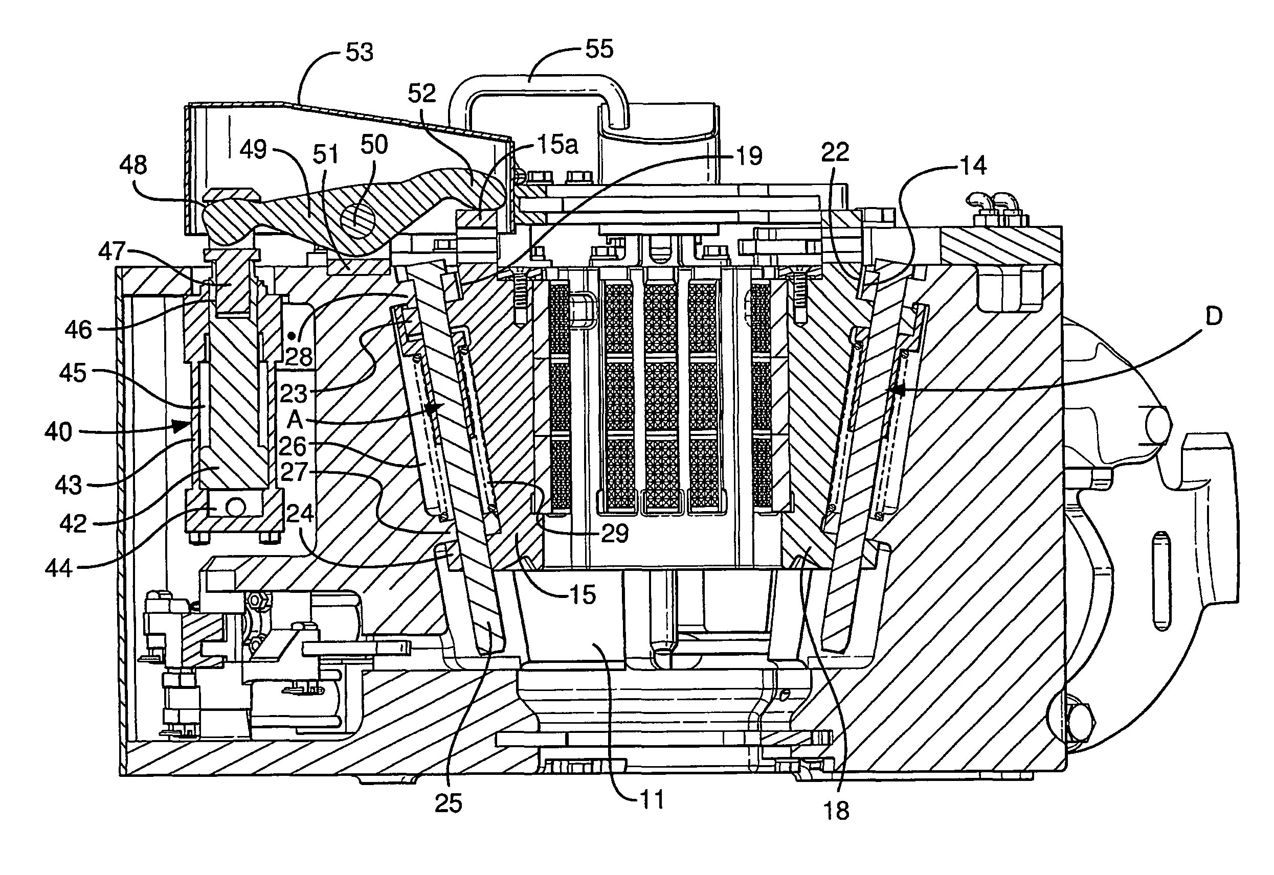
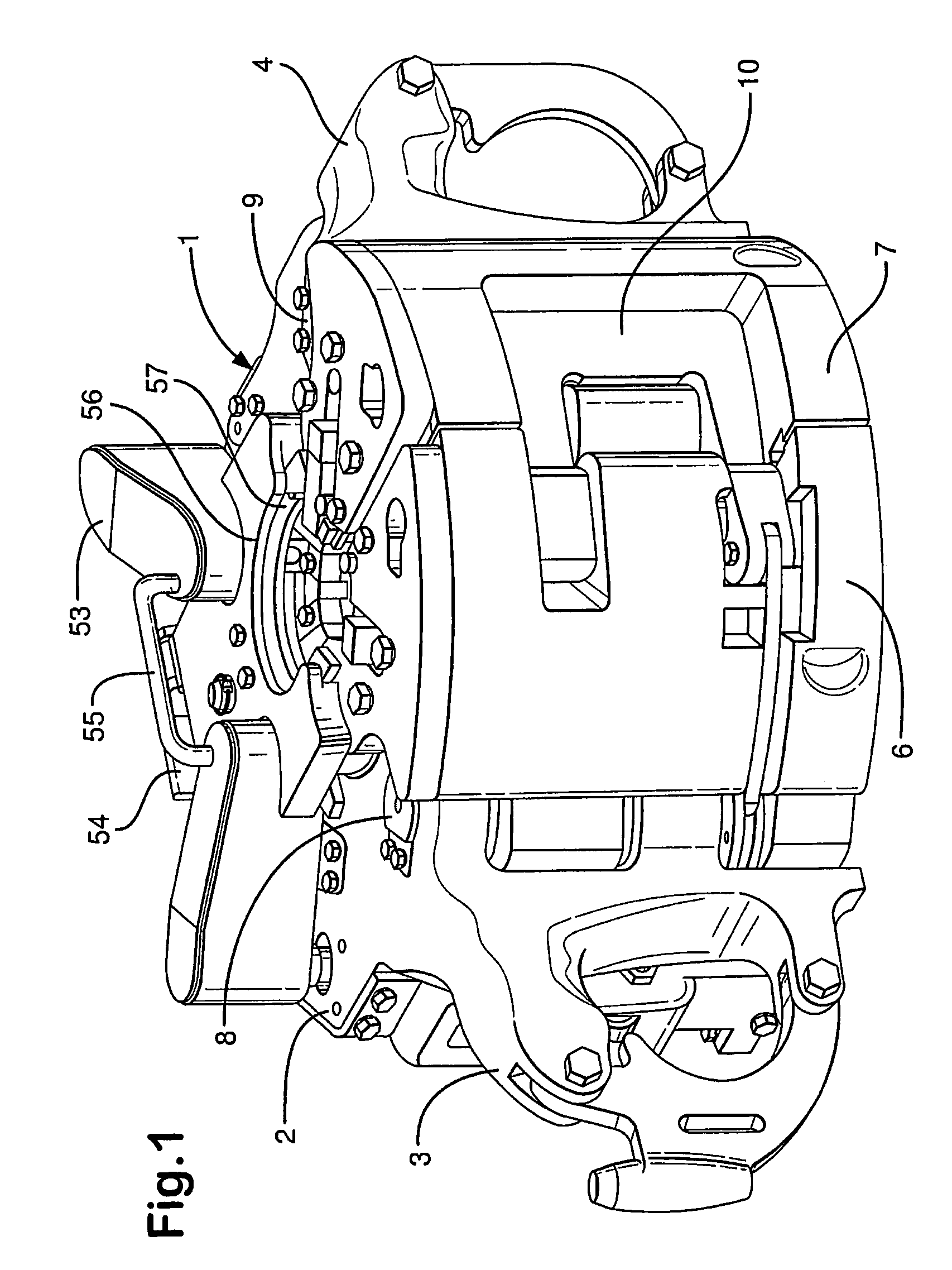
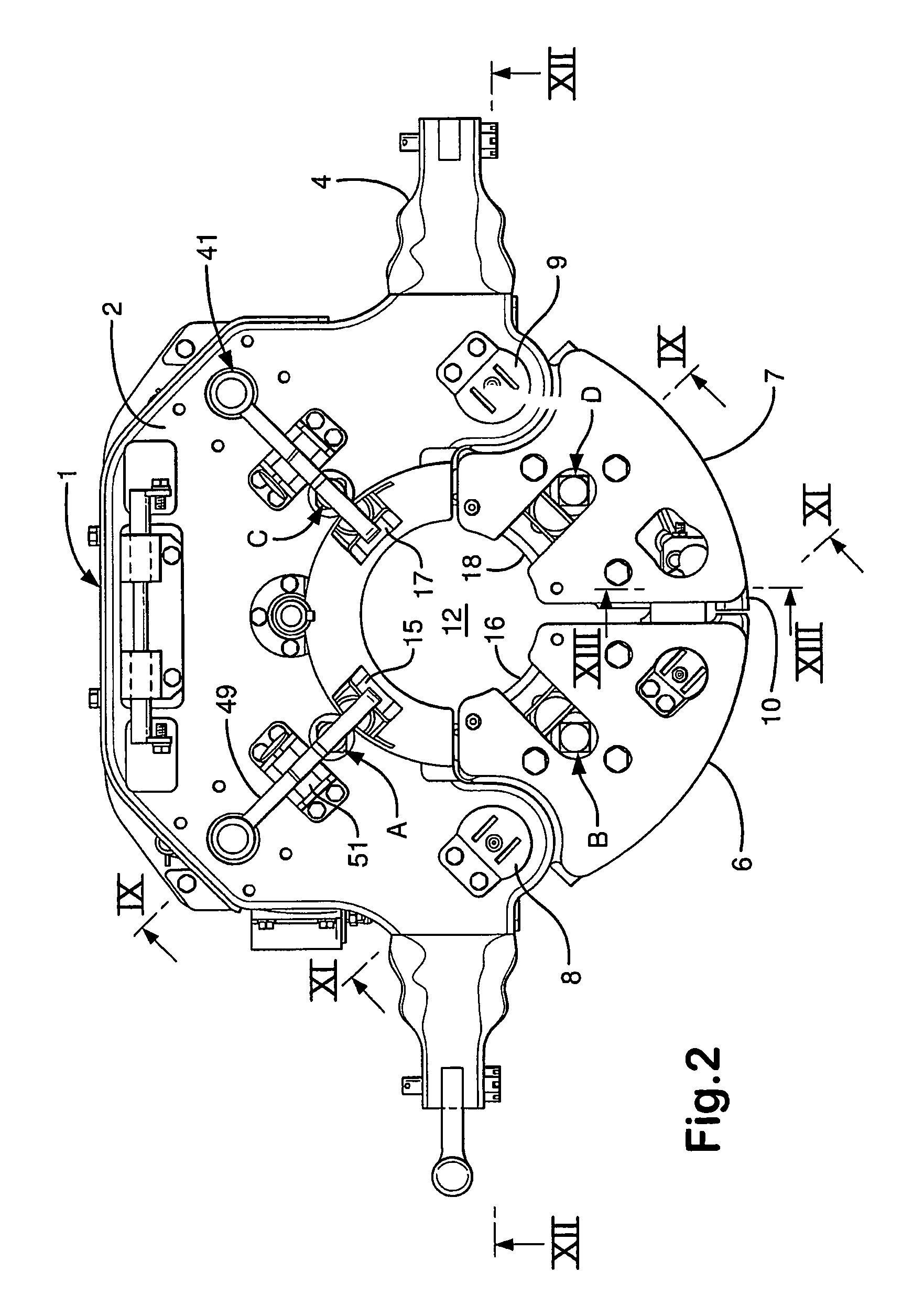
[0069]Referring to FIGS. 1 to 13, there is shown an apparatus of the present invention generally identified by the reference numeral 1. In the art of handling pipes on a drilling rig, the apparatus 1 is often referred to as an “elevator”. The elevator 1 comprises a part cylindrical body 2 having lifting ears 3 and 4 arranged on opposing sides of the housing 2 for connection to a pair of bails 5, as shown in FIG. 14. Doors 6 and 7 are hinged to the body 2 on hinge pins 8 and 9. A latch 10 is provided to latch the two doors 6 and 7 together to inhibit the doors 6 and 7 from inadvertent opening due to operational mechanical shocks.

[0070]The body 2 has a part frusto-conical inner surface 11 which tapers inwardly from the top to the bottom of the body 2 at an angle of approximately ten degrees from vertical to define an open throat 12, see FIGS. 1 and 10. From FIG. 7 it can be seen that the part frusto-conical inner surface 11 subtends approximately one hundred and eighty degrees. The do...


PUM


Abstract

An apparatus for handling pipes, the apparatus, in certain aspects, having a body having a tapered surface and at least a first slip and a second slip slidable on the tapered surface, a slip actuator for setting said at least first slip and said second slip, said first slip and said second slip having interengaging elements such that upon actuation of said slip actuator, said first slip is set and said second slip is set by the interengaging elements transferring setting force from the slip actuator through said first slip to said second slip; and methods for using such an apparatus.

Description

CROSS-REFERENCE TO RELATED APPLICATIONS[0001]This is a nationalization of PCT application Ser. No. PCT / GB 2004 / 050001 filed 16 Aug. 2004 (Int'l Publication No. WO 2005 / 106185, published 10 Nov. 2005) which claims priority from U.S. Application 60 / 567,235 filed 1 May 2004—both of which applications are incorporated fully herein for all purposes and from both of which the present invention and application claim priority under the Patent Laws.BACKGROUND OF THE INVENTION[0002]1. Field of the Invention[0003]The present invention relates to an apparatus and method for facilitating handling pipe and handling pipe strings particularly, but not exclusively, to an elevator for handling pipe on drilling rigs. The pipe may be a single section, stand or string of drill pipe, a single section, stand or string of casing, tubular, premium tubular, drill collars or pipe incorporating a well tool.[0004]2. Description of Related Art[0005]In the drilling, completion and work over of a borehole in the o...

Claims


Application Information

Patent Timeline
Patent Type & Authority Patents(United States)
IPC IPC(8): E21B19/10E21B19/07
CPCE21B19/07E21B19/10
Inventor SONNEVELD, LEENDERT ADRIAAN MARINUSKRIJNEN, ANTONIUS DIMPHENA MARIADE PONT, ALBERT PATRICK JOZEF MARIASCHATS, MICHAEL ANTOON HERMANDE LAAT, CORNELIS WILHELMUS JACOBUSVAN RIJZINGEN, JOHANNES WILHELMUS HENRICUS
Owner VARCO I P INC
Why Eureka
Try Eureka