Vibration reduction apparatus for power tool and power tool incorporating such apparatus

a technology of vibration reduction and power tools, which is applied in the direction of manufacturing tools, portable power-driven tools, drilling machines, etc., to achieve the effect of adjusting the tension of the biasing means with a reasonable degree of sensitivity

Inactive Publication Date: 2010-07-27
BLACK & DECKER INC
View PDF56 Cites 11 Cited by
  • Summary
  • Abstract
  • Description
  • Claims
  • Application Information

AI Technical Summary

Benefits of technology

[0021]By attaching the handle means of a power tool to axle means via at least one arm and connectors, the advantage is provided that vibrations in the handle are damped more effectively than in the prior art. Furthermore, the vibrations are damped without conversion into vibrations in a different direction. In particular, when vibrations cause the movement of one end of the handle, the axle means, in combination with the or each arm and connectors, transfers some of that vibration to the other end of the handle means whilst the biasing means damps the vibration. As a result, the rocking motion of the handle means, as experienced in the prior art, where the spring at one end of the handle means is able to be compressed whilst the spring at the other end of the handle can be extended, is reduced. Consequently, the uncomfortable and potentially damaging flexing of the wrist is similarly reduced. Furthermore, because of the linkage of arms and connectors with the handle means, the further advantage is provided that the handle means is not caused to twist in the hand of the user. Thus the reduction or removal of one form of vibration does not introduce an alternative undesirable vibration. This combination of advantages provides a significantly and surprisingly improved reduction in the vibrations of this type of apparatus compared to that experienced in the prior art.
[0038]By providing the adjusting means such that the rotation of the cam results in movement of the biasing means in a direction which is substantially parallel to axis of rotation of the cam, the advantage is provided that a large movement of the lever can result in a small movement of the portion of the biasing means which is engaged with the cam. This therefore allows for considerable sensitivity in the adjustment in the tension of the biasing means.

Problems solved by technology

Thus the reduction or removal of one form of vibration does not introduce an alternative undesirable vibration.

Method used


Image

  • Vibration reduction apparatus for power tool and power tool incorporating such apparatus
  • Vibration reduction apparatus for power tool and power tool incorporating such apparatus
  • Vibration reduction apparatus for power tool and power tool incorporating such apparatus

Examples


Embodiment Construction

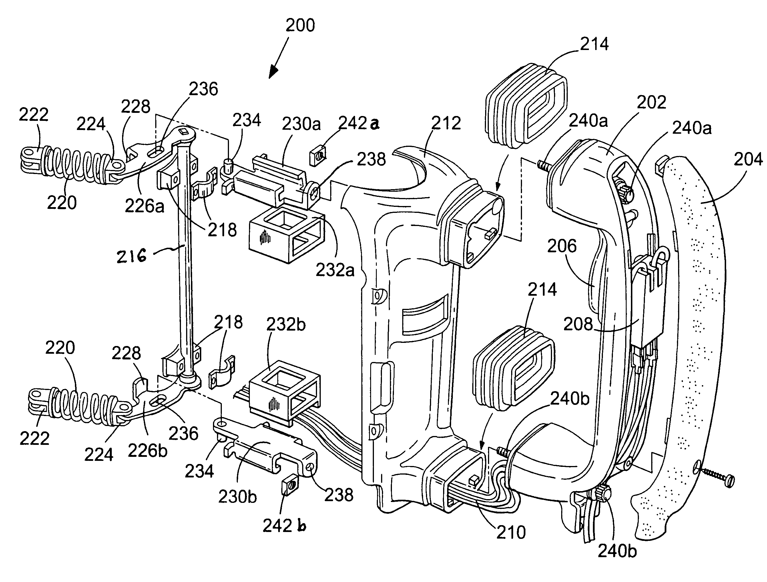
[0049]Referring to FIG. 3, a handle assembly 200 of a first embodiment of the invention for use as part of a power hammer (not shown) has a handle 202 which has a rubberised gripping portion 204. Handle 202 also has a trigger 206 which activates switch 208 and provides power to the hammer mechanism via cables 210.

[0050]Handle 202 is mounted to the housing 212 of the power tool, only a portion of which is shown in FIG. 3, and handle 202 is capable of limited movement relative to housing 212. Rubberised sleeves 214 cover the joint between handle 202 and housing 212. The handle assembly also has an axle 216 which is attached to the housing 212 by brackets 218 and is able to rotate relative to the housing 212 between a first position and a second position. Axle 216 is biased towards said first position by biasing means in the form of helical springs 220. Springs 220 are fixed relative to the housing 212 at first ends 222, whilst second ends 224 are able to move relative to the housing 2...


PUM

PropertyMeasurementUnit
biasing forceaaaaaaaaaa
linear movementaaaaaaaaaa
axis of rotationaaaaaaaaaa

Abstract

A power tool has a handle capable of limited movement mounted to its housing. An axle is rotatably connected to the housing and is movable between a first and second positions and is spring biased towards the first position. Arms are connected to and rotate with the axle. Connectors are slidably mounted within guides and are connected at one end to the arms and at the other end to the handle. Vibrations in the body of the power tool cause movement of one end of the handle, which causes movement of a connector and in turn movement of an arm. Movement of the arm causes rotation of the axle which therefore causes movement of the other arm. This in turn causes the related connector to slide within its guide and move the other end of handle. Thus, movement of one end of the handle is coupled to the other end.

Description

FIELD OF THE INVENTION[0001]The present invention relates to vibration reduction apparatus for power tools and to power tools incorporating such apparatus. The invention relates particularly, but not exclusively, to vibration reduction apparatus for power hammers, and to hammers incorporating such apparatus.BACKGROUND OF THE INVENTION[0002]Electrically driven hammers are known in which a driving member in the form of a flying mass is reciprocally driven in a piston, and impact of the flying mass against the end of the piston imparts a hammer action to a bit of the hammer. Such an arrangement is disclosed in European patent application EP1252976 and is shown in FIG. 1.[0003]Referring in detail to FIG. 1, the prior art demolition hammer comprises an electric motor 2, a gear arrangement and a piston drive arrangement which are housed within a metal gear housing 5 surrounded by a plastic housing 4. A rear handle housing incorporating a rear handle 6 and a trigger switch arrangement 8 is...

Claims


Application Information

Patent Timeline
Patent Type & Authority Patents(United States)
IPC IPC(8): B25D17/00B25D17/24B25D17/04B25F5/02
CPCB25D17/043B25D2222/57B25D2250/371
Inventor STIRM, MICHAELBECHT, REIMUNDHAHN, NORBERT
Owner BLACK & DECKER INC
Why Eureka
Try Eureka