Load equalizing rope termination and method

a rope termination and load technology, applied in the direction of buckles, snap fasteners, hoisting equipment, etc., can solve the problem of preventing the proper operation of the devi

Active Publication Date: 2010-07-27
JLG IND INC
View PDF26 Cites 9 Cited by
  • Summary
  • Abstract
  • Description
  • Claims
  • Application Information

AI Technical Summary

Benefits of technology

[0006]It would thus be desirable to develop structure cooperable with the rope termination that would prevent a load imbalance of the rope ends. The rope termination and method described herein utilize a rope termination fitting including one or more load equalizing support members. The support members receive a portion of the rope or an attachment to the rope to prevent the rope from an imbalanced load. The structure additionally ensures independence of the ropes as each is capable of supporting the load independently in the event one of the ropes fails.
[0007]In an exemplary embodiment of the invention, a load equalizing rope termination includes a pair of rope ends; a rope termination attached to the rope ends and defining an end section such as an end loop and a pair of rope leads; and a rope termination fitting. The rope termination fitting includes a base support member over which the end section is supported, and a pair of load equalizing support members disposed upstream of the base support member and over which the rope ends are supported. The engagement between the rope ends and the load equalizing support members prevents a load imbalance of the rope leads.
[0009]In another exemplary embodiment of the invention, a load equalizing rope termination includes a pair of rope ends; a rope termination attached to the rope ends and defining an end section and a pair of rope leads; and a rope termination fitting having structure coupled with the rope ends for preventing a load imbalance of the rope leads.

Problems solved by technology

A problem arises with this arrangement, however, if a load imbalance occurs on the rope ends.
In the event of such a load imbalance, the object to be moved may be skewed or otherwise unevenly displaced, which thereby may prevent proper operation of the device.

Method used


Image

  • Load equalizing rope termination and method
  • Load equalizing rope termination and method
  • Load equalizing rope termination and method

Examples


Embodiment Construction

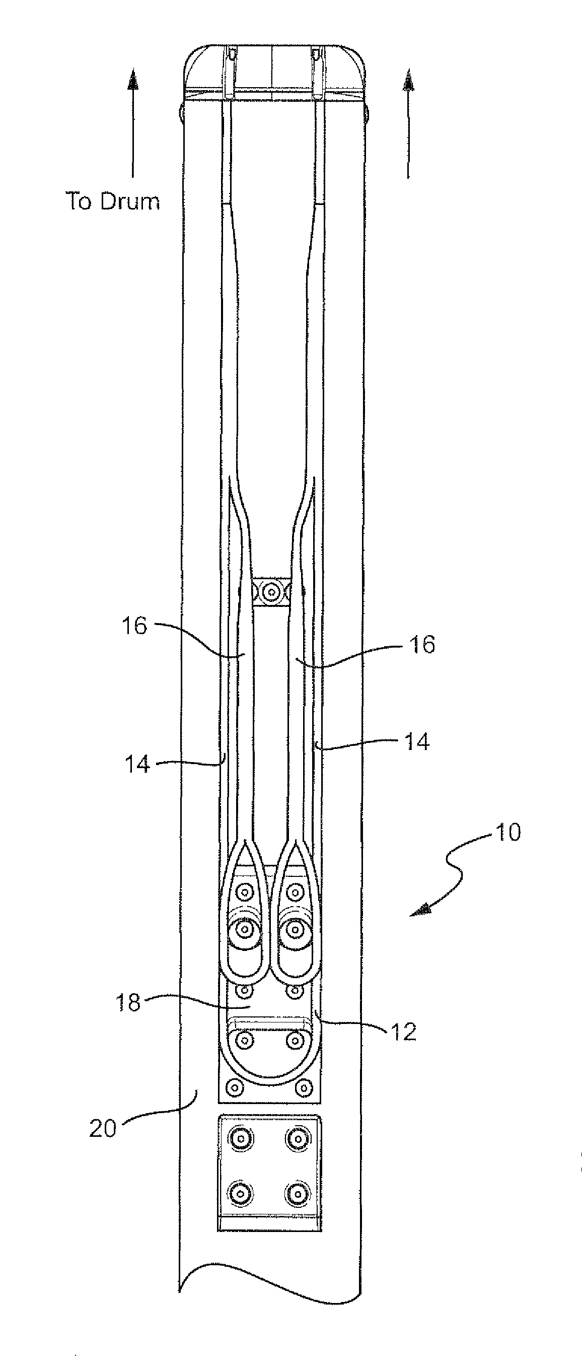
[0016]With reference to FIG. 1, like a conventional redundant arrangement, a load equalizing rope termination includes a pair of rope ends 16. The rope ends 16 are attached at an opposite end to a rotating drum or the like. The ropes are configured such that either rope is independently capable of supporting the load, thus providing an added margin of safety in the event that one of the ropes breaks.

[0017]The rotating drum or the like may be fixed and the load movable at the distal ends of the ropes; or the drum may be attached to the movable load and move with the load with the distal ends of the rope fixed; or a combination of both. In a preferred arrangement, the drum is fixed, and the load, such as a work platform or the like, is restrained to move along a load path (e.g., with wheels on rails). If the ropes 16 are not identical in length, one of the ropes will carry a disproportionate share of the load. This is particularly so if the ropes are high in stiffness such as wire rop...


PUM


Abstract

A load equalizing rope termination serves to prevent a load imbalance between a pair of rope leads of a rope termination. The rope termination includes an end section such as an end loop and the pair of rope leads attached to a pair of rope ends. A rope termination fitting includes a base support member over which the end section is supported, and a pair of load equalizing support members disposed upstream of the base support member and over which the rope ends are supported. The engagement between the rope ends and the equalizing support members prevents a load imbalance of the rope leads.

Description

CROSS-REFERENCES TO RELATED APPLICATIONS[0001](Not Applicable)STATEMENT REGARDING FEDERALLY SPONSORED RESEARCH OR DEVELOPMENT[0002](Not Applicable)BACKGROUND OF THE INVENTION[0003]The present invention relates to force distribution and load balancing and, more particularly, to a load equalizing rope termination and method that prevent a load imbalance on a pair of rope leads.[0004]A lifting or winch system is known where a driving pulley, cable, chain, tape, rope or the like (hereinafter “rope”) is attached to a rotating drum or other motive power source. At its end, the rope is secured to the object to be lifted or pulled. The drum is fixed relative to the object to be moved. As the drum is rotated, the rope is taken up around the drum, and the object to be moved is pulled.[0005]In order to provide a level of redundancy, a pair of ropes with respective rope ends may be secured between the drum and the object to be lifted. A problem arises with this arrangement, however, if a load i...

Claims


Application Information

Patent Timeline
Patent Type & Authority Patents(United States)
IPC IPC(8): B66D1/00
CPCB66D1/54Y10T24/3936Y10T24/3982
Inventor CAMPBELL, GEOFFREY GEORGEMCNEIL, ALEXANDER MCKECHRAN HARDIE
Owner JLG IND INC
Why Eureka
Try Eureka