Fossil-fueled power station comprising a carbon dioxide separation device and method for operating a fossil-fueled power station

a technology of carbon dioxide separation and power station, which is applied in the direction of electric generator control, machines/engines, mechanical equipment, etc., can solve the problems of large amount of energy required for carbon dioxide separation from fossil-fueled power stations, and it is not possible to extract the required large quantity of steam from the turbine at a suitable pressure, so as to reduce the energy loss of steam extraction

Inactive Publication Date: 2014-04-01
SIEMENS AG
View PDF5 Cites 7 Cited by
  • Summary
  • Abstract
  • Description
  • Claims
  • Application Information

AI Technical Summary

Benefits of technology

[0008]It is therefore the object of the invention to specify a device and a method for a fossil-fueled power station, for providing low pressure steam for a carbon dioxide separation device from a source other than the overflow line between the medium- and low-pressure stages, so that an unbalanced load in the power station process is avoided and the energy losses due to the extraction of the steam are largely minimized.

Problems solved by technology

The separation of carbon dioxide out of the exhaust gases from fossil-fueled power stations, such as for example combined cycle gas turbine (CCGT) power stations or coal-fired steam turbine power stations, requires a large amount of energy.
On the other hand, in the case of steam turbines with a single-housing medium- and low-pressure stage, it is not possible to extract the required large quantity of steam from the turbine at a suitable pressure.
The extraction of steam from other sources within the power station process is often not to be recommended, or is not possible in a suitable way.
Thus, for example, extraction from a reheater line on the steam turbine produces an unbalanced load on the boiler.
Extraction of higher grade steam for the carbon dioxide separation device must also be excluded, because this leads to unacceptable energy losses.

Method used


Image

  • Fossil-fueled power station comprising a carbon dioxide separation device and method for operating a fossil-fueled power station
  • Fossil-fueled power station comprising a carbon dioxide separation device and method for operating a fossil-fueled power station

Examples


Embodiment Construction

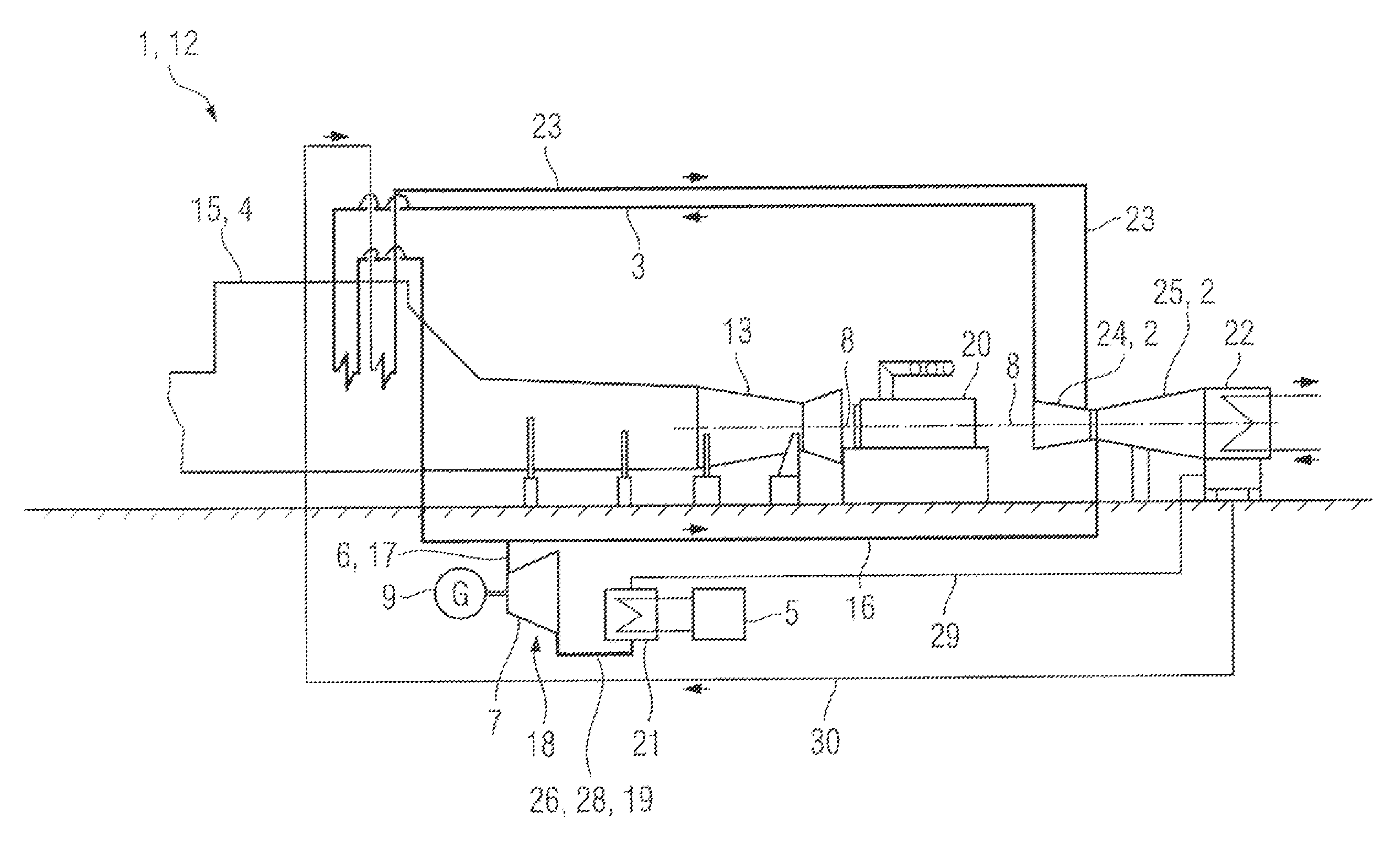
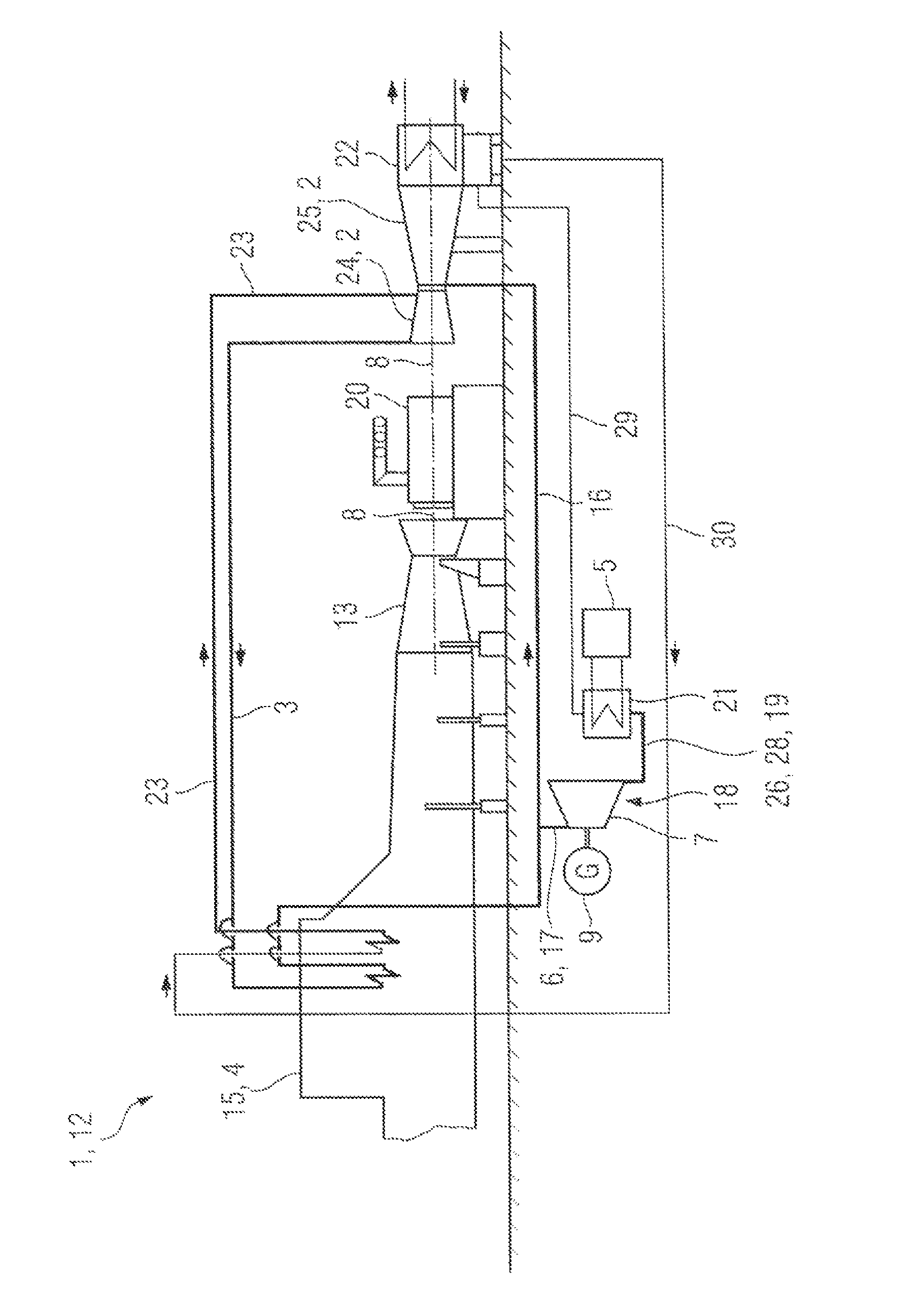
[0018]The figure shows the essentials of a fossil-fueled power station 1 with a heat exchanger 21 connected to a carbon dioxide separation device 5. The fossil-fueled power station 1 is here in the form of a combined cycle gas turbine (CCGT) power plant 12. The combined cycle gas turbine plant 12 is shown in simplified form, and here consists of a gas turbine 13, a steam turbine 2, a generator 20, and a steam generator 4 connected in the exhaust gas duct of the gas turbine, in the form of a heat recovery steam generator 15.The steam turbine 2 consists of a high pressure stage 24 and a medium- and low-pressure stage 25. The gas turbine 13, the generator 20 and the steam turbine 2 are located on a common shaft 8. Connected downstream from the steam turbine 2 is a condenser 22.

[0019]The high pressure stage 24 has a live steam feed connection from the steam generator 4 via a live steam line 23 and a steam return feed connection via a steam return line (cold reheater line) 3. Connected t...


PUM


Abstract

A fossil-fueled power station including a steam generator is provided. A steam turbine is mounted downstream of the steam generator via a hot intermediate superheater line and a carbon dioxide separation device. The carbon dioxide separation device is connected to the hot intermediate superheater line via a process steam line and a backpressure steam turbine is mounted into the process steam line.

Description

CROSS REFERENCE TO RELATED APPLICATIONS[0001]This application is the US National Stage of International Application No. PCT / EP2010 / 066518, filed Oct. 29, 2010 and claims the benefit thereof. The International Application claims the benefits of German application No. 10 2009 051 640.9 DE filed Nov. 2, 2009. All of the applications are incorporated by reference herein in their entirety.FIELD OF INVENTION[0002]A fossil-fueled power station including a steam generator, a steam turbine mounted downstream of the steam generator via a hot intermediate superheater line and a carbon dioxide separation device is provided. The carbon dioxide separation device is connected to the hot intermediate superheater line via a process steam line and a backpressure steam turbine is mounted into the process steam line.BACKGROUND OF INVENTION[0003]The separation of carbon dioxide out of the exhaust gases from fossil-fueled power stations, such as for example combined cycle gas turbine (CCGT) power station...

Claims


Application Information

Patent Timeline
Patent Type & Authority Patents(United States)
IPC IPC(8): F02C6/18
CPCF01K23/10Y02E20/16F01K23/14F01K17/04F01K7/22Y02E20/32
Inventor GRUMANN, ULRICHMUCH, ULRICHPICKARD, ANDREASROST, MIKE
Owner SIEMENS AG
Why Eureka
Try Eureka