Air decontamination method

a technology of air decontamination and air, which is applied in the direction of lighting and heating equipment, heating types, separation processes, etc., can solve the problems of chemical gases or vapours presenting a serious hazard

Active Publication Date: 2010-07-27
HYDROXYL TECH LTD
View PDF23 Cites 5 Cited by
  • Summary
  • Abstract
  • Description
  • Claims
  • Application Information

AI Technical Summary

Problems solved by technology

In addition to microbiological contaminants, chemical gases or vapours can present a serious hazard, either as a by-product of industrial processing or as a malicious attack through terrorism or chemical warfare.

Method used


Image

  • Air decontamination method
  • Air decontamination method

Examples


Embodiment Construction

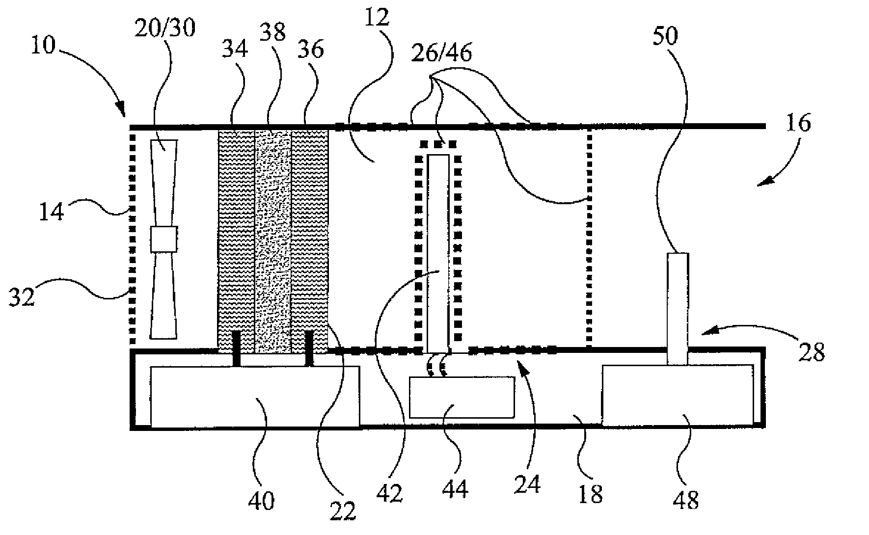
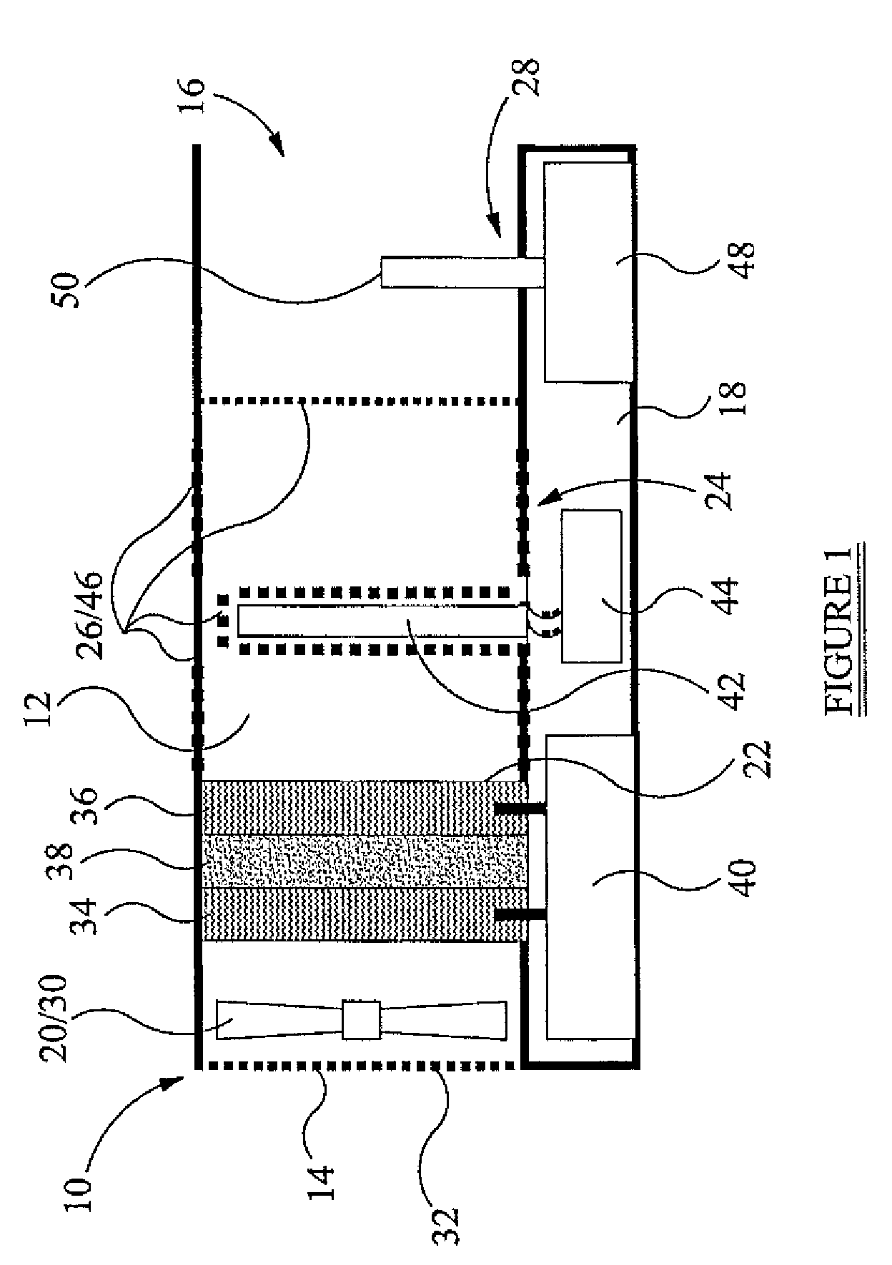
[0014]The air stream generator 20 is provided adjacent the air inlet 14 of the passage 12. The air stream generator 20, in this embodiment, is an electric fan 30 powered by mains electricity or battery packs (not shown) provided in the compartment 18 of the housing 10. As a safety measure, a grill 32 is provided across the air inlet 14 to prevent accidental access to the fan 30 while in operation.

[0015]The non-thermal plasma filter 22 is positioned adjacent the fan 30, downstream of the air inlet 14. The plasma filter 22 comprises a cathode 34 and anode 36, between which is sandwiched a dielectric 38. The cathode 34 and anode 36 are powered by a power supply unit (PSU) 40 housed in the compartment 18 of the housing 10.

[0016]The cathode 34 and anode 36 comprise reticulated (three dimensionally porous) conductive elements, in this case being aluminium and carbon composite. However, any rigid reticulated conductive or semi-conductive material could be used.

[0017]The dielectric 38 is ac...


PUM

PropertyMeasurementUnit
diameteraaaaaaaaaa
wavelengthaaaaaaaaaa
Air purityaaaaaaaaaa

Abstract

An air decontamination device comprising an air stream generator (20), a non-thermal plasma filter (22), an ultraviolet (UV) radiation emitting device (24), an ozone catalysing device (26), and a hydrocarbon emitter (28). The air stream generator (20) generates and directs an air stream through or across the non-thermal plasma filter (22), the UV radiation emitting device (24), the ozone catalysing device (26), and the hydrocarbon emitter (28). The plasma filter (22) produces free radicals by which contaminants in the air stream are nuetralised. The UV radiation emitting device (24) breaks down ozone in the air stream, catalysed by the ozone catalysing device (26). The hydrocarbon emitter (28) discharges an aromatic hydrocarbon into the air stream to preferentially react with residual ozone so that the air stream becomes suitable for human exposure. A method is also provided.

Description

FIELD OF THE INVENTION[0001]The present invention relates to a method of decontaminating air, and to a device for use with said method.BACKGROUND OF THE INVENTION[0002]Air purity and being able to consistently remove contaminants entrained in the air is extremely important, especially in supposedly sterile or hygienic environments, such as hospitals and kitchens. It is also beneficial having decontaminated air in doctors surgeries, and workplace environments making it more difficult for germs and disease to spread.[0003]In addition to microbiological contaminants, chemical gases or vapours can present a serious hazard, either as a by-product of industrial processing or as a malicious attack through terrorism or chemical warfare.SUMMARY OF THE INVENTION[0004]The present invention seeks to provide a solution to these problems.[0005]According to a first aspect of the present invention, there is provided a method of decontaminating air, the method comprising the steps of:[0006]a) direct...

Claims


Application Information

Patent Timeline
Patent Type & Authority Patents(United States)
IPC IPC(8): A61L9/00A62B7/08A61L9/015A61L9/20A61L9/22B01D53/32B01D53/66B01D53/86
CPCA61L9/015A61L9/20A61L9/22B01D53/32B01D53/66B01D53/8675B01D2259/818B01D53/007B01D53/8671B01D2251/104B01D2255/2073B01D2258/06B01D2259/4508B01D2259/804A61L2/00A61L9/16B01J19/08B01J19/123F24F3/16B01D53/86
Inventor MOLE, ALAN
Owner HYDROXYL TECH LTD
Why Eureka
Try Eureka